You must have observed how technology is changing at a fast pace. Presently, almost everyone in the world owns a mobile phone. Earlier, you required a landline phone to make a call, but that is now a thing of the past. With cell phones, you can communicate directly from anywhere. Every new day, we are witnessing novel wireless technology improvements. A wireless charger circuit, built using a printed circuit board (PCB), is among these latest tech advancements. It enables you to charge your phone without using a cable.
Do you know how this innovation works? We have summarized it all for you in this article, including insights into PCB design and the role of PCB assembly in creating efficient wireless charging solutions.
Contents
1. Wireless Charger Circuit Principle

Smartphone on a wireless charging pad, charger.
Wireless charging operates via the concept of mutual inductance. You, therefore, link the power source to the target device via inductive coupling.
The principle of inductance enables the creation of an electromotive force in a conductor. Through inductance, you can also experience an electromotive force in a nearby conductor. There are two kinds of inductance.
- Mutual conductance
- Self-conductance
You can experience mutual conductance via prompting a voltage to develop in another secondary coil using a primary coil. To achieve this, you need to place a current-carrying conductor near the other conductor. When you set this arrangement, a magnet flux develops in the primary coil. This flux, in turn, causes a voltage flow in the secondary coil. Consequently, you will achieve inductive coupling in the two conductors.
2. Wireless Charger Circuit Design

The Wireless charging of smartphone
Wireless charging technologies operate using a simple circuit connection. The key components that you need to set the circuit include a transformer, capacitors, resistors, diodes, voltmeters, and copper coils.
Setting a wireless power transfer will require you to establish two circuits.
-
Transmitter Circuit
First, you need a transmitter circuit. It is the power source that will induce wireless power transfer. Its key components include a DC source, transmitter coil, and an oscillator circuit. An oscillator circuit is made of n channel MOSFETS and 4148 diodes.
After introducing an input voltage to the oscillator, current flows through the coils and transistor at the drain terminal. As this happens, you will also induce a voltage flow at the transistor’s gate terminal. Thus, one of the transistors will switch on as the other one is off. You can calculate the operating frequency of this transmitter circuit using the formula F=1[2π(LC)]. L, in this case, is the inductance, and C represents the capacitance of the capacitors.

Copper Coils
-
Receiver Circuit
Secondly, you require a receiver circuit. The components of this circuit include a rectifier circuit, regulator, and receiver coil. To induce current transfer, you place the receiver circuit at some distance from the inductor. It will prompt the flow of an AC electrical current in the coil. This electrical current is not ready to use for wireless power solutions. You need to rectify it using the rectifier circuit. This circuit has a diode and a capacitor. Next, you need to regulate this alternating current to DC 5v using a regulator. You can now connect the power outlet of the regulator to the battery for wireless power solutions.
Special Offer: Get $100 off your order!
Email [email protected] to get started!
3. Wireless Charger Circuit Advantages
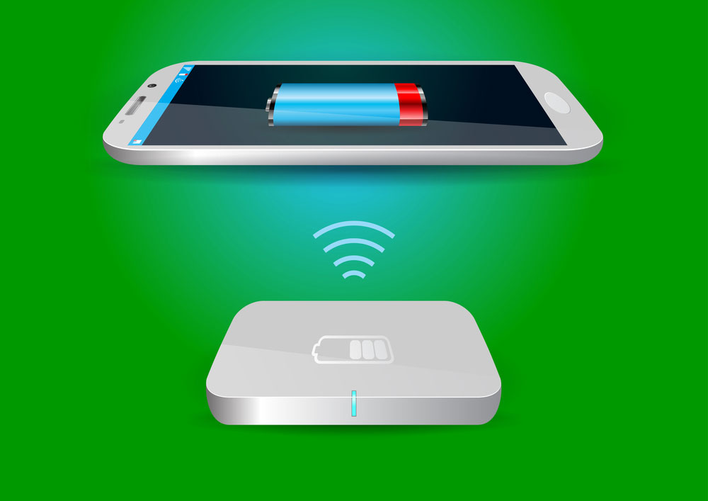
Wireless Battery Charger and Smartphone
There are several upsides to wireless power designs, especially if you get the connection right. The following are some advantages:
- Cordless connection. You do not have to worry about carrying your cord everywhere you go.
- It offers you universal compatibility. You can use the Qi wireless Charger circuit board to charge a wide range of devices.
- It guarantees safe connections. Since you do not need a cord, there is a limited risk of corrosion. Also, you avoid the risk of electrical faults that are synonymous with faulty charging cables.
- You are assured of durability. You do not need to keep plugging and unplugging devices. Therefore, you will have no tear and wear in your device’s charging sockets.
- You are done with overheating the phone. Immediately your device is fully charged, the wireless charger will go off. Thus, it will not overheat.
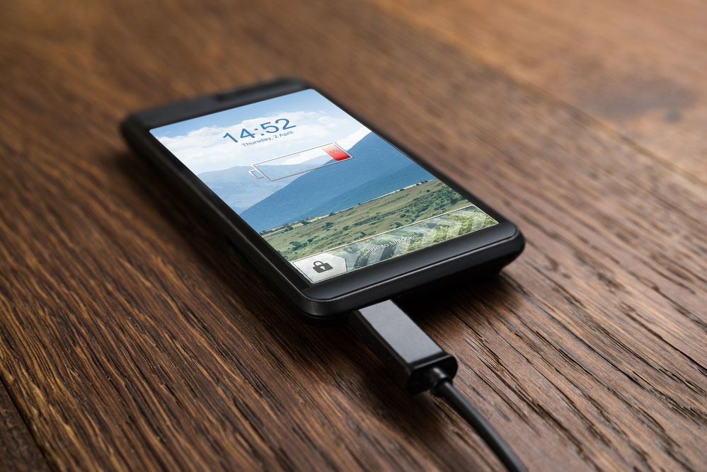
A phone charging using a cable
- It is easier to use and assemble than a plugin cable. All you need to do is to place your phone on the pad and it will immediately start charging. Assembling it is also straightforward.
Given these advantages, there are several ways that you can use a wireless charging lane. First, you can use it to charge various devices such as mobile phone batteries and Bluetooth headsets. You can also apply the wireless charging standard on platforms such as car charging systems. Lastly, the medical field can also use this technology.
4. Limitations of the Circuit
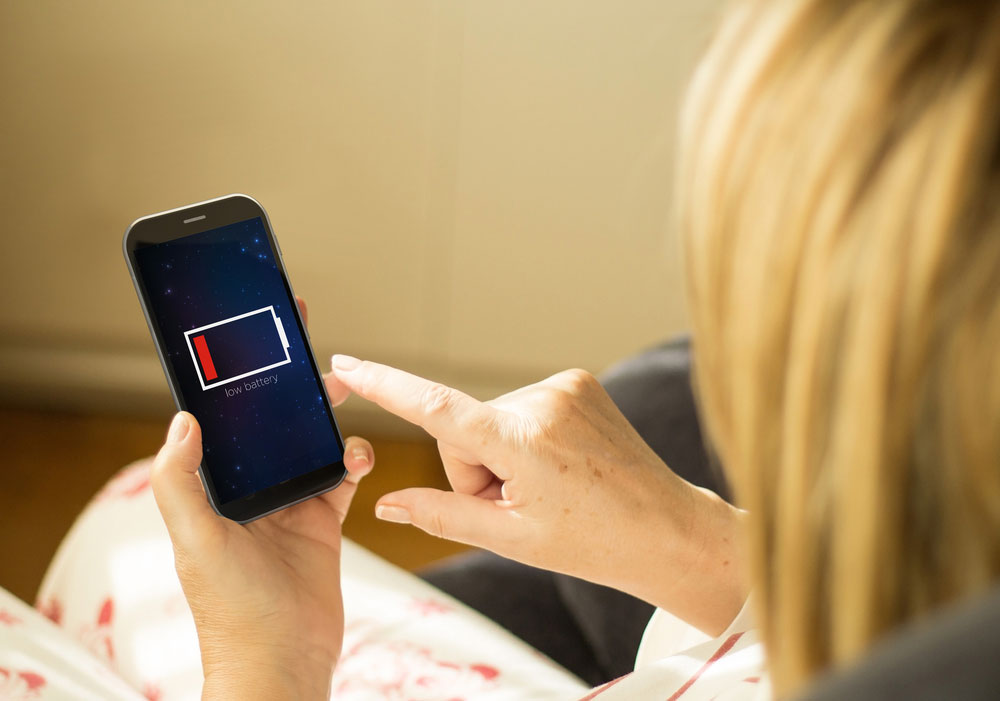
Smartphone on low battery
You are also set to meet some limitations when using a wireless charging lane. Some of them include:
- You will experience some power loss during the process of mutual induction. It is unavoidable as, unlike in the cable system, you cannot achieve complete power transfer. Therefore, you may not fully charge your cell phones as you would while using a cable charger.
- You are also limited to transferring power over short distances. A long cable means that you can charge your phone without necessarily being close to the charger. However, for the wireless charging standard, you need to modify the circuit to facilitate this.
5. The Bigger Coil Specifications in Wireless Charger Circuit, the Better?
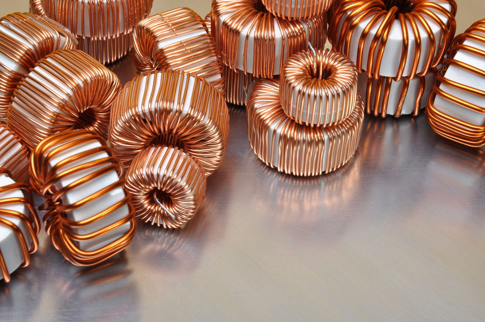
Figure 8: Electric Copper Coils
The bigger the coil that you use, the better. It will help you solve the challenge of the strength of the power supply.
With a bigger charger coil circuit board, you will increase the capacitance. It will ensure that the transmitter resonant frequency of the wireless cellphone charger circuit matches that of the receiver. Resultantly, you will induce a higher electrical current. It means that you have more power delivery during the actual power transfer phase.
Therefore, you must consider the coil size when designing wireless technologies. If you use bigger or many coils, the charge transfer will undoubtedly be higher. Similarly, a smaller coil means that you have less power. It implies that you must transmit over a short distance. Therefore, it would help if you make additional improvements to the wireless power consortium to increase output power.
Conclusion
In a nutshell, the future is wireless charging. You cannot simply ignore wireless charging technologies as they are very effective. All that you need is to secure yourself a wireless charger coil circuit board. It is also relatively straightforward. Simply consult ourPCB for further insights on this type of charger. We are ready to supply all your wireless charging systems need without fail.
Special Offer: Get $100 off your order!
Email [email protected] to get started!


