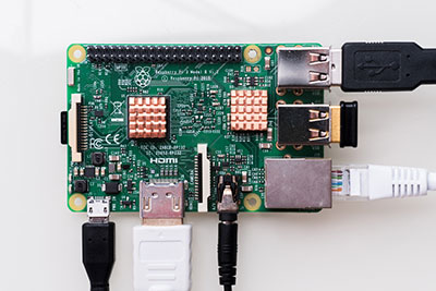
You can find FR4 (or FR-4) in almost every PCB, because it’s a convenient, affordable, and easy-to-use material. However, understanding FR4 material properties can help you make sure you’re using the best material during PCB manufacturing. Let OurPCB help you design and manufacture top-quality PCBs for whatever application you need. Get an online PCB quote today!
Contents
- How is FR4 used in the PCB Industry?
- Primary Insulating Material
- Copper Lamination
- Multilayer PCBs
- Surface Finishing
- What are the Different FR4 Material Types?
- Standard FR4
- High Tg FR4
- High-Frequency FR4
- High CTI FR4
- FR4 Without Copper Laminate
- G10
- What are the Properties of FR4 Substrate?
- Types of Dielectric Material
- Dielectrics Active
- Dielectrics Passive
- Dielectric Properties of FR4
- Typical Values of Dielectric Constant for FR4
- Factors Affecting Dielectric Constant
- What are the Thermal Properties of FR4?
- Glass Transition Temperature (Tg)
- Coefficient of Thermal Expansion (CTE)
- Thermal Conductivity
- Mechanical Properties of FR4
- What are the Differences Between FR4 Material and Rogers Material?
- Tips to Select the Right FR4 Material
- Get in Touch
How is FR4 used in the PCB Industry?
Primary Insulating Material
FR4 is used as the main insulating substrate in PCBs. It makes for a sturdy base that supports the copper traces, which create the actual circuits. The fiberglass-reinforced epoxy laminate material has high mechanical strength and electrical insulation, which is important for reliable PCB performance.
Copper Lamination
FR4 sheets are laminated with one or more layers of copper foil. It’s done using heat and adhesive, creating a strong bond between the copper and the FR4 substrate. The copper layers are then etched to form the circuit patterns you want. This process can create single-sided, double-sided, or multilayer boards.
Multilayer PCBs
Multiple layers of FR4 and copper are laminated together, separated by insulating layers of prepreg (pre-impregnated) materials. This is handy for creating intricate and high-density circuits that can handle advanced modern electronics.
Surface Finishing
Once the copper layers are etched, a protective solder mask is applied to the PCB to prevent oxidation and solder bridges during assembly. Common surface finishes include HASL (Hot Air Solder Leveling), ENIG (Electroless Nickel Immersion Gold), and OSP (Organic Solderability Preservatives).
What are the Different FR4 Material Types?
Standard FR4
Standard FR4 is the most common material used, with a good balance of mechanical, electrical, and thermal properties. It has a glass transition temperature (Tg) of around 130° C to 140°C, so it’s suitable for general-purpose applications with moderate heat demands.
High Tg FR4
High Tg FR4 is designed for high-heat environments. It has an elevated glass transition temperature, usually between 170° C and 180° C. This type is great for high-power and high-reliability applications, like automotive systems and power electronics, where the material must maintain its properties under higher temperatures.
High-Frequency FR4
High-frequency FR4 materials are optimized for radio frequency (RF) and microwave use. They have a lower dielectric constant and dissipation factor, which help minimize signal attenuation and boost signal integrity at high frequencies. It’s commonly used in telecommunications, aerospace, and radar systems.
High CTI FR4
High Comparative Tracking Index (CTI) FR4 materials offer the highest resistance to electrical breakdown and also have better thermal conductivity. They’re a good choice for applications that need fast heat dissipation and high electrical insulation, such as power supplies and industrial electronics.
FR4 Without Copper Laminate
This variant of FR4 doesn’t include a copper layer and is used mainly for insulating boards and mechanical supports. It has all the mechanical strengths of standard FR4, but is non-conductive.
G10
G10 is known for its toughness, high resistance to thermal shock, and excellent electrical insulation. This material is used in applications that need a solid core with robust mechanical and dielectric characteristics. Notably, FR4 is flame retardant, whereas G10 is not.
What are the Properties of FR4 Substrate?
FR4 substrates have important properties that make them suitable for a wide range of different uses in electronics.
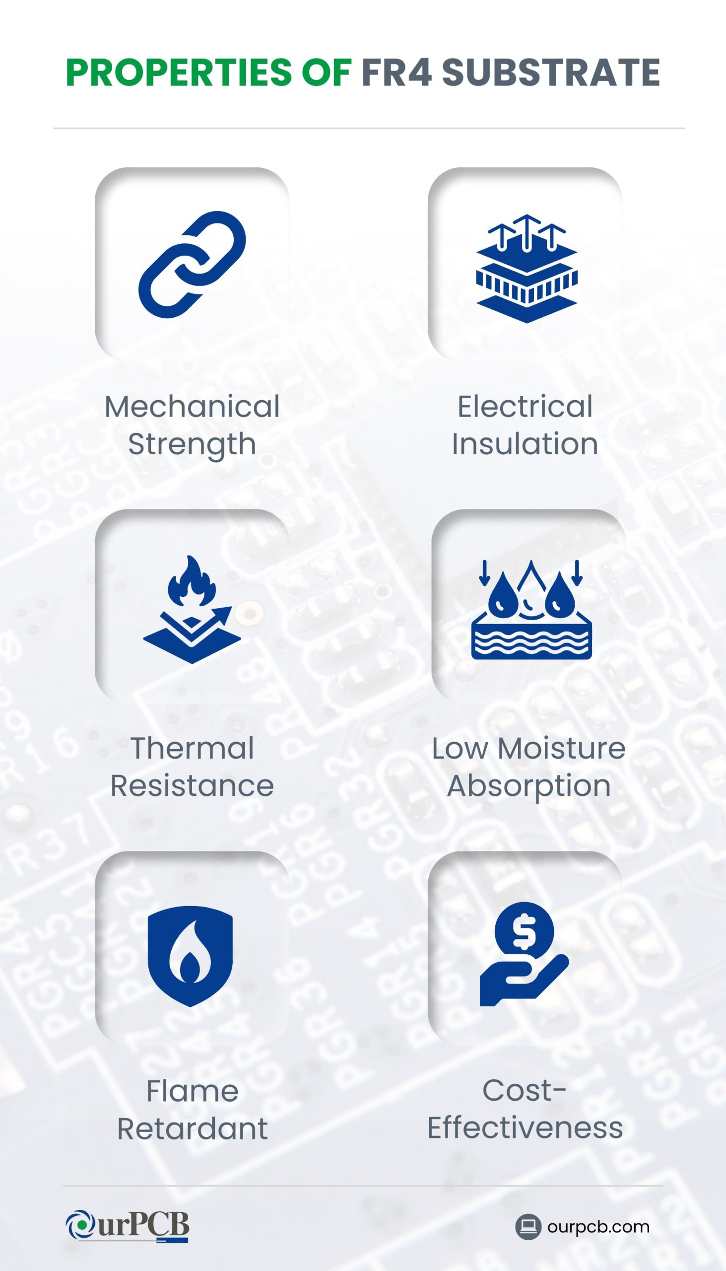
- Mechanical Strength: Known for their high mechanical strength, which maintains durability and resistance to physical stresses during manufacturing and use.
- Electrical Insulation: FR4 has excellent electrical insulation, helping to prevent electrical shorts and making sure the circuit operates reliably.
- Low Moisture Absorption: Low water absorption helps maintain the electrical and mechanical properties of FR4 even in humid environments.
- Thermal Resistance: FR4 can withstand high temperatures without a problem, so it’s suitable for use where heat dissipation is a concern.
- Flame Retardant: As a flame-retardant material, FR4 reduces the risk of fire, increasing the safety of electronic devices.
- Cost-Effectiveness: FR4 is relatively affordable compared to other high-performance PCB materials.
Types of Dielectric Material
There are two main types of dielectric materials: active and passive.
Dielectrics Active
Active dielectrics can control electrical behavior within circuits. They can adjust and manipulate how electrical signals work, making them useful in components like capacitors and transistors. Active dielectrics are an important part of tuning circuits and enhancing signal processing.
Dielectrics Passive
Passive dielectrics provide insulation and mechanical support without affecting the electrical signals. They’re used to prevent electrical shorts and protect components. They maintain the integrity of circuits by acting as barriers between conductive parts.
Special Offer: Get $100 off your order!
Email [email protected] to get started!
Dielectric Properties of FR4
In FR4 circuit boards, the dielectric constant (Dk) is a measure of a material’s ability to store electrical energy in an electric field. In PCBs, the dielectric constant affects how quickly electrical signals can travel through the material.
A stable dielectric constant is important for maintaining signal integrity, especially in high-frequency applications. This keeps signal propagation consistent and reduces signal loss.
Dielectric dissipation, or loss tangent (Df), measures energy lost as heat. For FR4, a low Df is preferred. Higher Df can lead to signal attenuation and noise, impacting overall PCB performance.
Dielectric strength, measured in volts per unit thickness, is the maximum electric field the dielectric can handle before breaking down or conducting electricity.
Typical Values of Dielectric Constant for FR4
The FR4 PCB board has a dielectric constant (Dk) of around 3.9 to 4.8. It can vary slightly depending on the specific formulation and manufacturing process. The impacts of this Dk value include:
- Signal Speed: A higher dielectric constant slows down the propagation speed of electrical signals. Designers must account for this when designing high-speed circuits.
- Impedance Control: The dielectric constant affects the impedance of transmission lines on the PCB. Consistent Dk values help maintain the desired impedance levels, which is important for signal integrity in high-speed and high-frequency applications.
- Capacitance: The dielectric constant influences the capacitance between conductors in a PCB.
- Propagation Delay: Materials with higher dielectric constants cause increased propagation delays, impacting the timing of signal transmission.
- Signal Integrity: Variations in the dielectric constant can lead to signal distortion and loss, especially in high-frequency applications.
- Loss Tangent: High dielectric constants often have higher loss tangents, which means more energy is lost as heat, reducing efficiency.
- Crosstalk: A higher Dk can increase crosstalk between adjacent traces, which can degrade signal quality and lead to errors in high-speed digital applications.
- Electromagnetic Interference (EMI): High dielectric constants can result in greater EMI, which can interfere with the performance of nearby electronic devices and systems.
Factors Affecting Dielectric Constant
Resin Composition
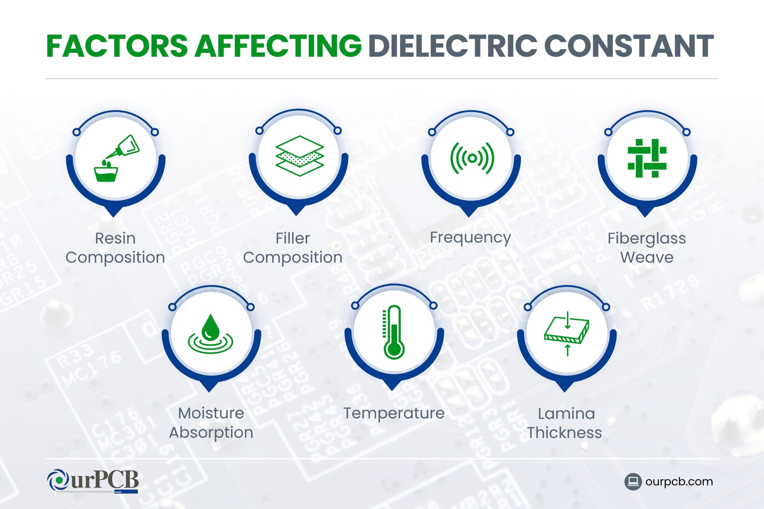
The specific epoxy resin system used in FR4 has a big influence on its dielectric constant (Dk). Different resin formulations across manufacturers can result in slight variations in Dk values. The type of resin impacts the overall electrical performance of the FR4 material.
Filler Composition
The dielectric properties of FR4 change based on the filler content within the epoxy resin. Higher filler percentages generally increase the composite Dk. Different types of fillers used in the resin can also change thermal and mechanical properties, influencing the overall performance of the substrate.
Frequency
The dielectric constant of FR4 decreases with rising frequency due to polarizability effects. Usually, a 10 to 20% reduction in Dk is seen over the frequency range of 1 MHz to 10 GHz. This reduction plays a big role in high-frequency applications, where precise control of signal integrity is necessary.
Fiberglass Weave
The weave pattern of the glass fabric in the laminate construction can create minor anisotropies in the dielectric constant. These variations make a difference in high-precision applications, as they can affect the uniformity of electrical performance across the PCB.
Moisture Absorption
Moisture increases the dielectric constant because water has a very high Dk. This is a major concern in humid environments, because absorbed moisture can affect the electrical properties of the PCB, affecting its performance and reliability. Proper sealing and protective coatings can help fix this issue.
Temperature
The dielectric constant exhibits a negative temperature coefficient, decreasing linearly with rising temperature due to increased molecular motion. As the temperature rises, the thermal motion of molecules in the material increases, weakening their polarization and reducing the dielectric constant. This effect must be managed to maintain signal integrity across varying thermal conditions.
Lamina Thickness
The number and thickness of laminate sheets can change the composite dielectric constant based on the ratio of glass, resin, and air. Thicker laminates may have different dielectric properties compared to thinner ones, due to variations in their construction.
What are the Thermal Properties of FR4?
Glass Transition Temperature (Tg)
The glass transition temperature (Tg) of FR4 is the temperature at which it changes from a rigid state to a more flexible one. Tg usually ranges from 130° C to 180° C. This property determines the maximum operating temperature of the PCB. Exceeding Tg can degrade the material’s mechanical and electrical properties, possibly leading to failure.
Coefficient of Thermal Expansion (CTE)
The coefficient of thermal expansion (CTE) measures how much FR4 expands with temperature changes. Below Tg, the CTE is low, but it increases above Tg. High CTE values can cause mechanical stress, affecting vias and solder joints, especially in high-temperature environments.
Thermal Conductivity
FR4 has a low thermal conductivity, typically 0.25 to 0.4 W/m·K. This means it doesn’t dissipate heat well, which can lead to hotspots and affect component performance. Effective thermal management, like using heat sinks and thermal vias, is an important step in managing heat in FR4 PCBs.
Mechanical Properties of FR4
- Tensile Strength: FR4 has a tensile strength of about 70,000 psi, is highly durable, and resistant to breaking under tension. This high strength is perfect for applications where mechanical stress is a concern.
- Flexural Strength: FR4’s flexural strength is also around 70,000 psi, so it can withstand plenty of bending without cracking. This property helps maintain PCB integrity under mechanical stress.
- Impact Resistance: FR4 offers excellent impact resistance, absorbing shocks and impacts without a lot of damage. Depending on the design, this can make it suitable for applications exposed to physical impacts or vibrations.
- Dimensional Stability: FR4 maintains its shape and size under fluctuating temperature and humidity conditions, providing exceptional dimensional stability.
What are the Differences Between FR4 Material and Rogers Material?
| FR4 | Rogers Material | |
|---|---|---|
| Composition | Woven fiberglass cloth with epoxy resin binder | Thermoset ceramic-filled PTFE composite |
| Dielectric Constant (Dk) | 4.2 to 4.6 | 2.2 to 10.2 |
| Dissipation Factor (Df) | 0.02 to 0.03 | 0.0009 to 0.002 |
| Thermal Conductivity Performance | Handles temperatures up to 266° F (130° C) | Handles temperatures up to 536° F (280° C) |
| Moisture Absorption | Higher absorption rates of 0.1 and 0.2% | Lower absorption rates of 0.02 to 0.08% |
| Advantages |
|
|
| Disadvantages |
|
|
| Applications |
|
|
| Cost | Cost-effective | Higher cost |
Tips to Select the Right FR4 Material
During FR4 PCB fabrication, material selection is the key to creating an effective board. Here’s what the experts at OurPCB say you should consider when choosing the right material.
- Operating Temperature: Select high Tg (glass transition temperature) FR4 for high-temperature applications, up to 170° C or more.
- Thickness Requirements: Choose the appropriate thickness based on the application’s need for rigidity or flexibility.
- Electrical Performance: For high-frequency applications, use low-loss FR4 materials with a low dielectric constant (Dk) and dissipation factor (Df) to reduce signal loss.
- Moisture Resistance: Make sure you select FR4 PCB material with good moisture resistance for use in humid environments to keep up their integrity and performance.
- Mechanical Properties: Select FR4 that can handle mechanical stresses like flexing, drilling, and expansion in heat.
- Environmental Impact: Choose environmentally friendly FR4 materials that comply with the relevant standards for being flame retardant and durable.
- Cost and Performance Balance: Balance cost and performance based on project requirements; standard FR4 PCB base material is cost-effective, but specialized FR4 offers high performance at a higher cost compared to standard FR4.
Get in Touch
Chances are high that you’ll end up using FR4 in PCB design and PCB assembly. It’s popular for a reason, and as long as you choose the right type for your application, your circuit boards will perform well and last a long time.
Back to top: FR4 Dielectric Constant
Special Offer: Get $100 off your order!
Email [email protected] to get started!


