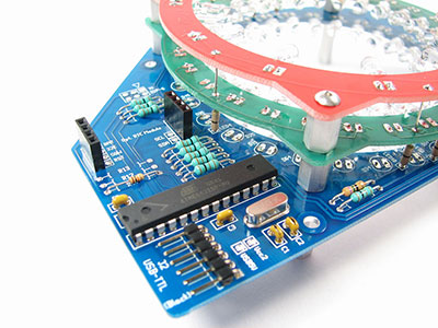
Also known as a Cable TV signal amplifier, a TV antenna booster provides access to more and clearer television programs. TV signal boosters are useful in remote areas such as RV parks that experience weak signals from the designated TV transmitter. Naturally, signal losses occur due to cable resistance and the splitting of signal to multiple TVs; hence the antenna amplifier helps fix such issues.
In regard, the article will dive deep into how you can make or repair a TV signal booster by elaborating on its components, structure, operation, and application.
Contents
1. The Purpose of Doing This Project
Some of us experience poor TV reception even after installing a good wireless TV antenna. For that reason, using a TV antenna amplifier boosts the signal on your TV aerial. The TV antenna booster strengthens the transmission speed of the existing over-the-air broadcast TV signals. For instance, the UHF (ultra-high frequency) antenna booster circuit amplifies a signal of the UHF band from 400 MHz to 850 MHz.
You do not have to purchase an expensive signal booster just because you live in a region unable to be reached by television broadcast transmitters. It is a simple project that requires basic materials and very minimal DIY skills to create common antennas.

(a picture of a frustrated man over poor tv signal)
2. What are the Antenna Circuit Project Preparation Materials?
Various antenna TV amplifiers circuits require different components. But, the basic materials that you need are transistors, capacitors, resistors, and a power source. For this project, we will use:
- 2 - NTE107 rf transistors.
- 5 - 100 to 120 pf capacitors
- 1 - 1k resistor
- 2 - 47k resistors
- 1 - 3.3k resistor
- 1 - 10 to the 12-volt power source
- Assorted wires for connections

(an image of a person assembling materials on a circuit board)
Special Offer: Get $100 off your order!
Email [email protected] to get started!
3. Assembling a TV Antenna Booster
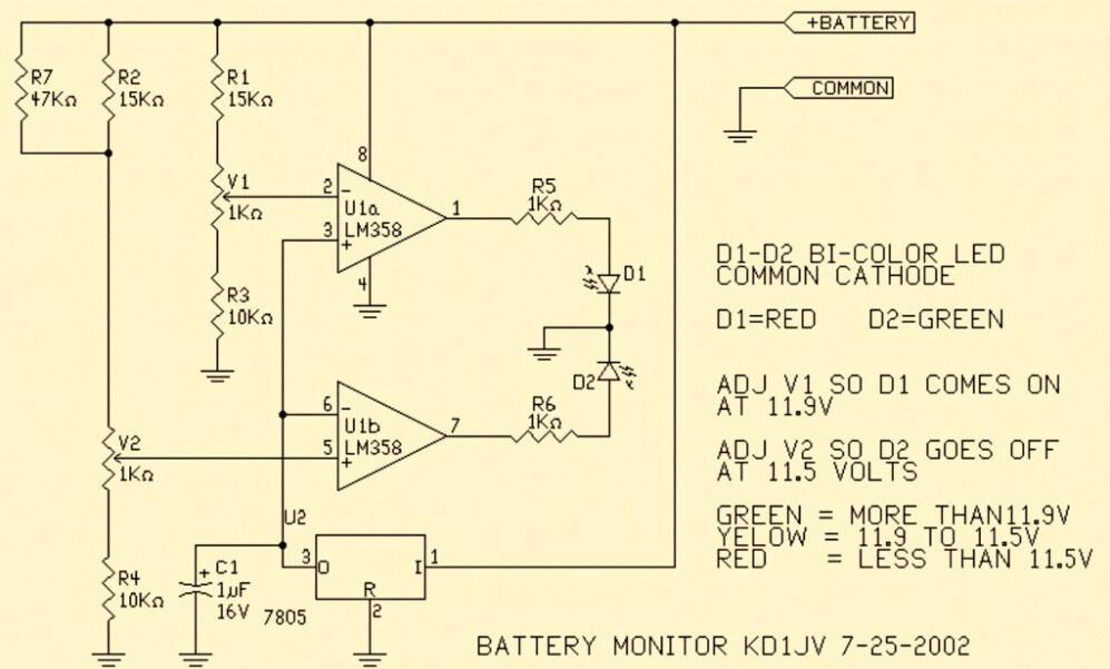
Assemble the circuit on a good quality PCB and make sure to shield the transistors from other components. Place the circuit in a metal box and connect the ground to the box to reduce noise. Also, use the 75Ohm coaxial cables at the input and output of the circuit.
The current consumption of the circuit ranges from 10 to 15mA. The circuit is fed through the cable using a choke coil to prevent the DC voltage from entering the television. Note that this is for an indoor antenna circuit; for areas with weaker signals, use an outdoor antenna. Additionally, for better performance, use a regulated power supply.
(an image of an circuit diagram of TV booster amplifier)
4. TV Aerial Booster Circuit Operating
There are different types of antenna signal boosters, but the TV aerial amplifier is specifically designed to be used with a television receiver. Television reception is based on the antenna as well as the transmitter.
The TV aerial booster works by amplifying all signals, whether good or electrical noises and interference from other transmitters. To reduce the unwanted signals, properly install the antenna masts, use galvanized cable and 75 Ω coaxial cable as they are less susceptible to interference.
5. TV antenna Amplifier Application
Typically, TV aerial boosters are used to improve the quality of a signal received by the television hence:
- HDTV antennas are used to get more channels
- Digital TV antenna circuits are utilized in digital TV applications

(an image of a TV transmitter in remote areas)
Conclusion
It is important to note that using the wrong antenna amplifier can worsen things. You mostly need an antenna booster; if the signal is borderline poor, then it can be amplified to a sufficient level that you can get a good picture.
I hope you have found the article informative and helpful in understanding your signal issues and antennas working for television reception. Contact ourPCB for more Instructions about antennas or if you need more elaborations on TV signal boosters.
Special Offer: Get $100 off your order!
Email [email protected] to get started!


