Printed circuit boards have proven highly useful in numerous applications. A key factor determining a PCB’s application is how its electrical components were mounted. Requesting a PCB quotation online helps you understand the costs and details of assembly services, including the techniques and materials involved.
You also learn how THT compares to other mounting processes like SMT and gain tips on choosing between the two.
Read on to learn more.
Contents
THT vs. SMT vs. SMD
Firstly, let us define each of these mounting technologies.
THT Technology
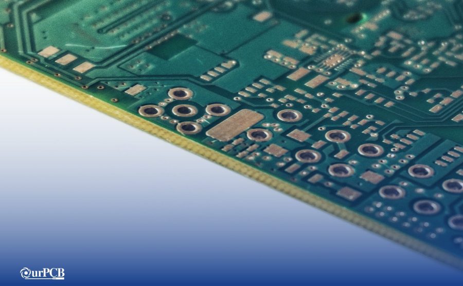
THT(through-hole technology) refers to mounting electronic components onto a circuit board through drilled holes.

Electronic components mounted on a PCB using THT.
In THT, a manufacturer drills holes into a PCB and consequently inserts leads into these holes. The manufacturer will then solder the leads on pads on the other side of the circuit board.
A manufacturer can solder the leads with the aid of wave soldering apparatus or a process known as reflow soldering.
In addition, through-hole technology has radial lead components such as ceramic capacitors and axial details.
Through-hole technology falls into three categories
- Single-ended- Package has pins at one end
- Double-ended- Package has pins at two ends
- Pin Grade Array
THT has proved more effective when making interconnections between circuit board layers and has replaced older methods like the pinpoint technique.
THT has also played a key role in PCB assembly.
SMT Technology
SMT stands for Surface mount technology.
It is a method in which manufacturers mount electronic components such as resistors, transistors, and capacitors on the surface of a PCB.
Moreover, SMT utilizes electronic elements without leads or small leads, and the components, including their solder joints, are on one side of the PCB.
Surface mount technology follows a simple working process.
First, a manufacturer aligns a PCB stencil on the circuit board surface and, using a squeegee, uniformly applies solder paste on the pads.
The manufacturer will then use a pick and placing machine to mount electronic components on the circuit boards in allotted places.
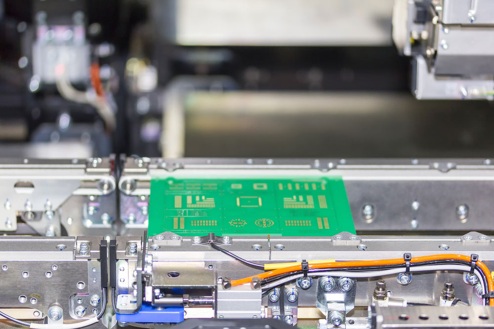
A circuit board on the conveyor of an SMT pick and place machine.
Finally, the manufacturer will place the circuit board into a reflow oven.
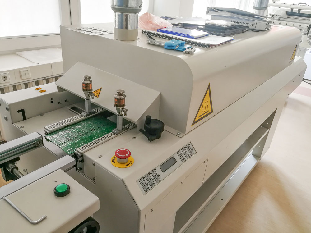
A PCB was moving into a reflow machine after assembly.
Infrared light melts the solder paste in the reflow oven, and thus, solder joints form. After which, the circuit boards go through assembly and test checks.
SMD
SMD is an abbreviation for Surface mount device, referring to an electronic component directly mounted on a printed circuit board.
The SMD electronic elements are relatively small and consist of chip resistors, diodes, network resistors, etc.
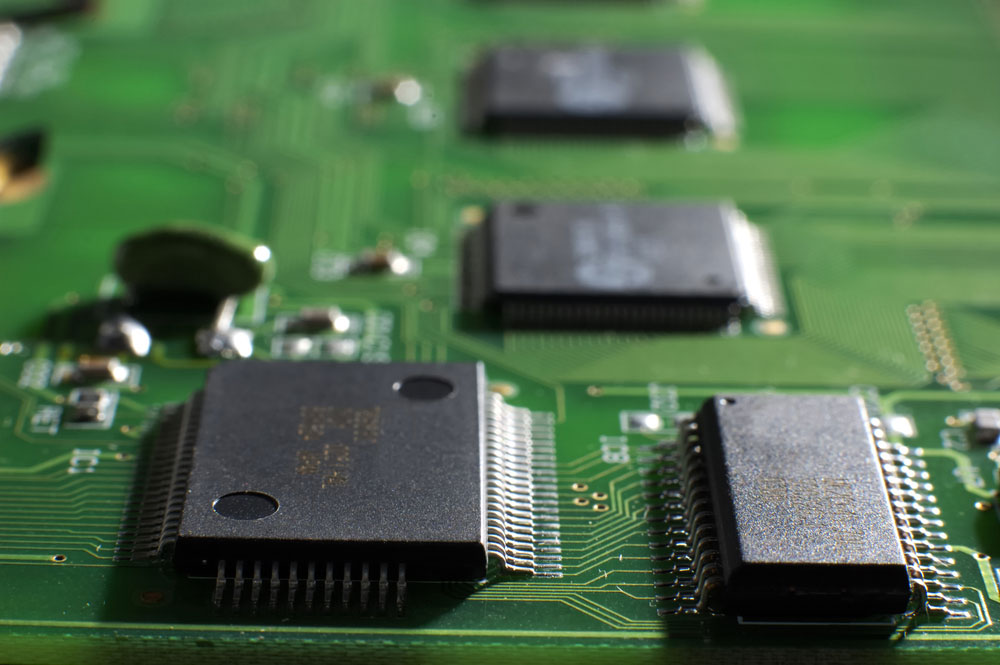
An SMD chip on a memory board
Through-Hole Technology vs. Surface Mount Technology
Below, we compare and contrast THT and SMT.
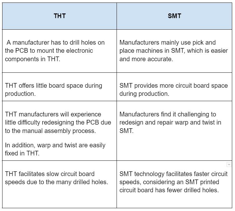
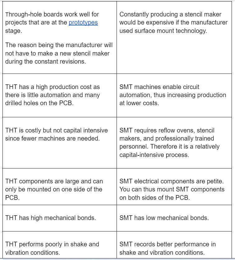
The SMD vs. SMT
SMT refers to the process of mounting electronic elements. While SMDs are electronic elements placed on a PCB.
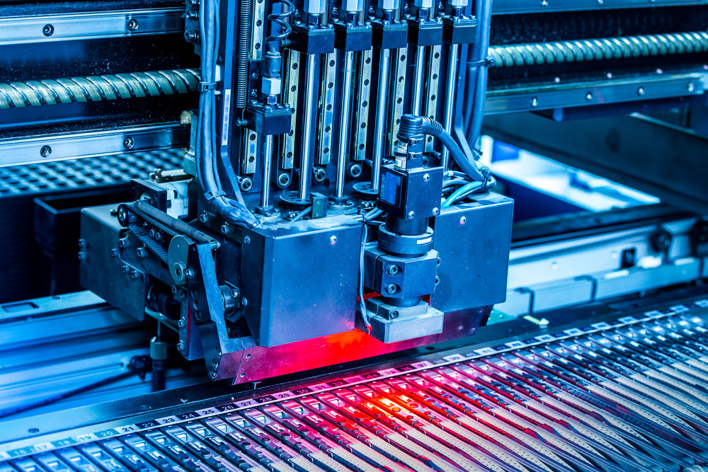
A surface mounting technology machine at work
Also, surface mount technology easily allows manufacturers to place surface-mount devices on a printed circuit board.
Special Offer: Get $100 off your order!
Email [email protected] to get started!
Advantages and Disadvantages of THT
Advantages
- Strong mechanical bond
- Wear and tear-resistant
- Suitable for quick prototyping
- High thermal shock resistance
Disadvantages
- It utilizes a lot of space.
- Slow operating speeds
- Expensive
- Reduces multilayer boards routing area
- Highly involving
- Requires circuit board drilling
Advantages and Disadvantages of SMT
Advantages
- Faster assembly & Reliable soldering
- Improved mechanical performance
- Small PCB size
- Has increased component density
- Cheaper production costs
Disadvantages
- Small lead sizes can be tough to repair.
- Requires expensive machinery and skilled personnel
- Minimal heat tolerance
- Weaker boards
THT vs. SMT Process: How to choose?
After comparing THT and SMT, it may be challenging to decide which of the two processes to use.
Below are some factors you can consider to aid you in decision-making.
Board design
Surface mount technology will work well on complex printed circuit boards and is cheaper, but for a simple PCB, THT works best.
Area of operation
THT would suit industrial printed circuit boards and more significant electrical components like transformers that experience immense heat, mechanical stress, and pressure.
Through-hole components strong solder joints will enable them to withstand the pressure.
Budget
As earlier stated, through-hole technology needs many drilling holes, making it an expensive process.
Nevertheless, surface mount technology is capital intensive but has lower production costs in bulk production.
To make a single PCB, you can use THT, whereas for bulk PCB production SMT would be best suited.
Finally, you can combine both SMT and THT processes when assembling to make a strong, reliable, and affordable PCB.
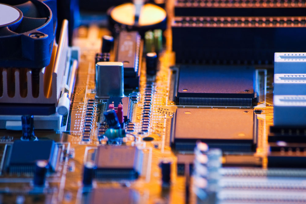
A computer board was made using both SMT and THT mounting processes.
Summary
Currently, many manufacturers use SMT LINE in PCB production, but THT still works better than SMT in some applications.
Therefore, whether you decide to use SMT or THT or combine both methods will depend directly on your intended PCB manufacturing service.
Back to top: THT Mounting
Special Offer: Get $100 off your order!
Email [email protected] to get started!


