Digital devices, logic gates, microcontrollers, and the like have specific logic voltages that determine whether the input is a logic high (1) or a logic low (0). Therefore, for such devices to deliver the expected condition, their inputs must have the right setting or bias. The components that can help you achieve this bias are pull-up and pull-down resistors. A resistor's primary function is to reduce current flow, but it can also serve as a voltage divider. It reduces the voltage flowing into the digital device.
Such a form of control is critical in digital devices, and we will take a closer look at these two components to differentiate them and see how they work.
Contents
- What are Pull Up and Pull Down Resistors?
- How Do Pull-Up Resistors Work?
- The Functions of the Pull-up Resistor and Pull-down Resistor
- To Avoid Malfunctions by Improving Circuit Stability
- To Increase The Output Pin's Load Capacity
- How To Calculate Values for Pull-up and Pull-down Resistors
- Calculating Actual Values For Pull-Up Resistors
- Calculating Actual Values For Pull-Down Resistors
- Pull Up vs. Pull Down Resistor: What is the Difference?
- Arduino Digital Input Pull-Up Resistor Tutorial
- Hardware Configuration
- Software Configuration
- Typical Applications for Pull-up and Pull-down Resistors
- Picking up Principle of Pull-up Resistor and Pull-down Resistor
- Summary
What are Pull Up and Pull Down Resistors?
In a nutshell, pull-up and pull-down resistors are critical components used to bias the inputs of digital gates, micro-controllers, and ICs correctly. If there is no input condition on the gates, correct biasing prevents random floating.
Digital logic gates usually contain multiple input and output pins, and these need a correct setting (low or high) for the digital circuit to work as required. Pull up and pull down resistors ensure the circuitry delivers the expected switching condition by pulling the input signal to a known state.
How Do Pull-Up Resistors Work?
Think of an ICs input signal pin connected to the VDD (circuit's positive supply voltage) via a resistor and another resistor connecting this input to the ground. The grounded resistor forms the input pin impedance, and when combined, the two make up a voltage divider.
A pull-up resistor connection to a digital chip
Comparing it to a standard voltage divider, the pull-up resistor in this circuit is equivalent to R1, while the input impedance is R2.
A voltage divider circuit diagram
Using the voltage divider formula, you can calculate the input pin voltage with the button not pushed using the following.
V OUT = V IN x R2 / (R1 + R2)
Since VDD is the input/supply voltage in the pull-up circuit and the output voltage is the voltage at the input signal pin, the formula becomes:
V PIN = V DD x R IMPEDANCE / (R PULL UP + R IMPEDANCE)
The Functions of the Pull-up Resistor and Pull-down Resistor
Pull-up and pull-down resistors have two functions. These include:
To Avoid Malfunctions by Improving Circuit Stability
A digital logic circuit can malfunction when you press the switch's button if the resistor does not pull it up to a high level. This malfunction is due to the microcontroller's pin-level remaining uncertain at the power-on moment.
To Increase The Output Pin's Load Capacity
Peripheral circuits have a minor influence on the digital course if the output is high because it does not attain a VCC state. This situation affects the regular operation of the entire microcontroller board system. However, a pull-up resistor improves the pin's driving ability.
Special Offer: Get $100 off your order!
Email [email protected] to get started!
How To Calculate Values for Pull-up and Pull-down Resistors
It is unnecessary to pick a specific resistance value, but it must fall within the acceptable range. Each microcontroller has a clear cut line that shows the limits of its logic high and logic low. Therefore, you need to understand the logic voltage first before calculating the values for these resistors.
Once you know these voltages, use Ohm's law (V=RI or R=V/I) to calculate the resistance values in the following manner.
Calculating Actual Values For Pull-Up Resistors
When using pull-up resistors, voltage is the value left after subtracting the minimum V accepted as high from the supply voltage. On the other hand, the current is the max current that can sink in the logic pins. Manufacturers give the logic voltage to determine the low and high limits for each device, so replace the values in the following formula:
R PULL-UP = (V SUPPLY - V H (min)) / I SINK
Calculating Actual Values For Pull-Down Resistors
We still use Ohm's law formula but with adjusted values. The purpose of a pull-down resistor is to ensure a low logic signal input, so you must attain a logic low. Therefore, the voltage value should be the maximum V accepted as a logic low. On the other hand, the current is the max current sourced by the digital pin.
R PULL-DOWN = (V L (max) - 0)/ I SOURCE
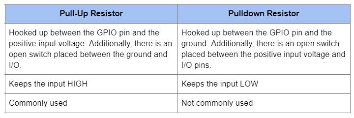
Pull Up vs. Pull Down Resistor: What is the Difference?
You can get the difference between a pull-up and pull-down resistor by looking at their names, but here is a detailed comparison between the two.

Arduino Digital Input Pull-Up Resistor Tutorial
If you want to get practical to understand the workings of the pull-up resistor, set up the following Arduino project. You need these components:
- Arduino board

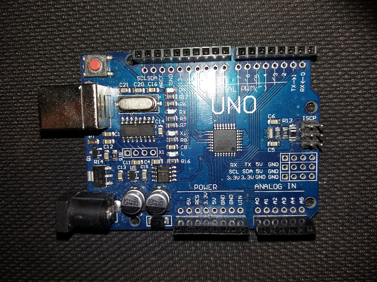
An Arduino UNO R3 microcontroller
Source: Wikimedia Commons
- Arduino IDE
- Breadboard
- Toggle switch or button
- Two wires
Hardware Configuration
Arduino UNO configuration to test the internal pull-up resistor
The toggle switch sits on the breadboard. Connect one wire to the ground and one leg of the button. Use the other wire to connect the digital pin D2 of the Arduino UNO to the other leg of the toggle switch.
Software Configuration
Step 1: Connect the Arduino board to your computer. After that, open the IDE and establish 9600 bits of data using the following line of code.
Serial.begin(9600);
Step 2: Next, initialize the digital pin as the input with the built-in pull-up resistor enabled using this code.
pinMode(2, INPUT_PULLUP);
Step 3: Convert pin 13 to an output pin so that you can use its onboard LED to show the output.
pinMode(13, OUTPUT);
Step 4: Create a variable to hold the signal data coming from the switch.
int sensorVal = digitalRead(2);
Step 5: After Arduino has read the switch data, print this information on the screen using the following code.
Serial.println(sensorVal)
If everything is functioning correctly, you should see a stream of "0" when you close the switch and a stream of "1" when you open it.
Step 6: Lastly, turn on the LED at pin 13 when the switch is HIGH (open) and turn it off when LOW (closed) using the following code:
if (sensorVal == HIGH) {
digitalWrite(13, LOW);
} else {
digitalWrite(13, HIGH);
}
A snippet of the Arduino code for configuring the board’s internal pull-up resistor
Typical Applications for Pull-up and Pull-down Resistors
The most common use is when interfacing an input or switch with a logic device or a microcontroller. However, most microcontrollers nowadays have programmable pull-up and pull-down resistors built-in, eliminating the need for these external components. Therefore, you can connect such devices directly with the switch.
Pull-up resistors are generally preferred and used than the pull-down type, and they can remain operational even when the logic device is not providing current.
The components also come in handy when you want to feed a controlled input current into a resistive sensor before the analog to digital conversion of the output signal.
I2C protocol buses require pull-up resistors to enable the signal pin to act either as an input or output. If disconnected from the bus, the cork floats in a high-impedance state.
As for pull-down resistors, you will likely find them on outputs to deliver a known output impedance.
Resistors
Picking up Principle of Pull-up Resistor and Pull-down Resistor
Generally, the resistance in pull-up resistors should be in the range of 1k to 10k. But how do you pick the exact value? Use the following points:
- When using a limited power supply, such as a battery, the resistor should have a high value (10k to 100k) to minimize the leakage current.
- The resistor's value should be high from the perspective of the chip's sinking capacity.
- If building a high-speed circuit, high pull-up resistance might flatten the edges.
- If you require sufficient driving current, use low resistance for pull up (1k to 10k). As stated earlier, this is the generally recommended range, so you should use the higher values (10k to 100k) only if you have a specific reason to use high resistance.
The actual resistance value is not that critical, so you don't need a complex formula to determine it. But keep in mind that high resistance values are weak pull-ups while low resistance values are strong pull-ups. It might seem counter-intuitive, but a low resistance allows more current to flow, making the pull to the supply stronger.
Summary
In conclusion, pull-up and pull-down resistors are critical for the accurate performance of digital devices because it keeps the input lines from floating. Even though the functions and workings of the two are different, their purpose is to provide control at the input pins and are essential when building such circuits.
That said, most digital devices have these resistors built-in, so you won't have to attach them manually. However, if you want to build such a circuit from scratch, contact us with your design, and we will assemble the device at a reasonable price.
Special Offer: Get $100 off your order!
Email [email protected] to get started!


