For many tech fanatics and students, the line follower robot is the major option they normally get experience with and learn about robotics projects. Designing them is a straightforward process as the path is visible and predefined. Therefore, in this article, we will understand how the Line follower robots work, mostly when integrated with different components.
Contents
- What is a Line Follower Robot?
- How To Make an Arduino Line Follower Robot?
- Constituents Needed
- Project Block Circuit Diagram
- Making Arduino Line Follower Robot
- Line Follower Robot using Microcontroller
- Raspberry Pi Line Following Robot
- How Does an IR Line Following Robot work?
- Applications of Line Follower Robot
- Summary
What is a Line Follower Robot?
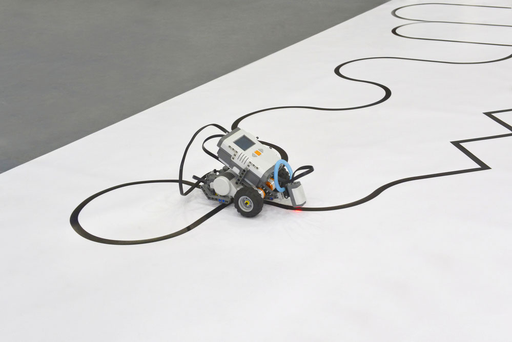
A line follower robot is an automatic appliance capable of detecting and following a path outlined on the surface. With a prearranged pathway, it can either have a visible magnetic field or a highly contrasting color. Basically, with their IR (infrared ray) sensors connected underneath them, these robots can sense the line. Besides, it has specific transmission devices that transmit data to the processor. After receiving the processor's data, it chooses the right command and sends it to the operator. Hence, the robot will then have a lane to follow.
How To Make an Arduino Line Follower Robot?
Constituents Needed
- IR Sensor Unit X 2
- Connecting Wires
- Arduino UNO or Aruino Nano
- Robot Chassis
- Battery Voltage Connector
- Battery Receptacle
- L293D Motor Driver IC
- Black insulation Tape
- Power Supply
Project Block Circuit Diagram
In this project, we divide the line follower robot into 4 blocks as follows;
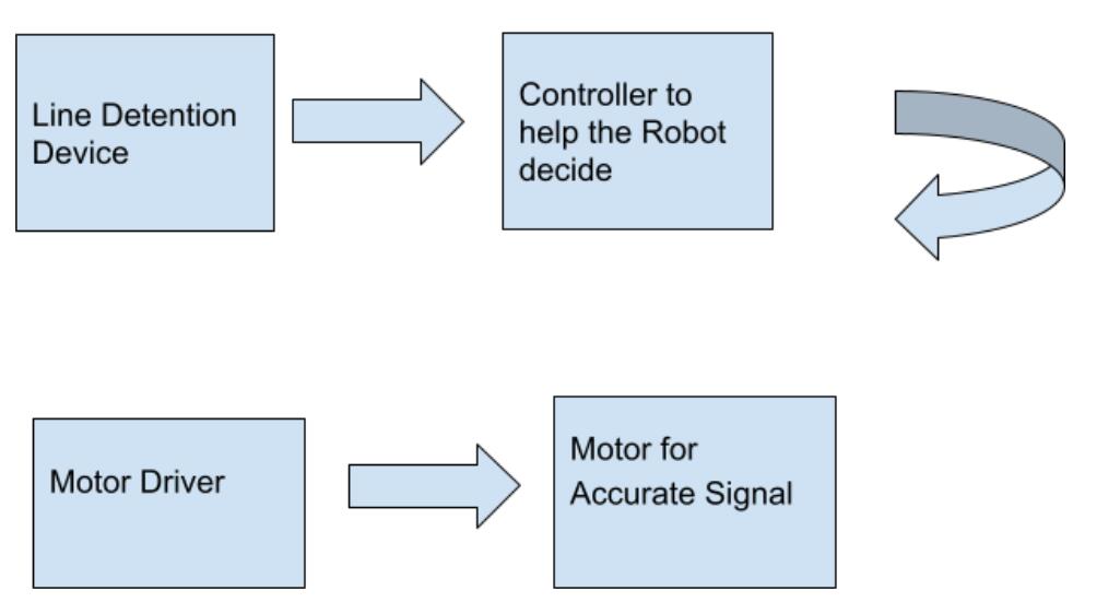
Line Follower Robot Block Diagram
Explanation of Block Diagram
- Arduino UNO (Controller); will be the central regulator. Therefore, it receives data within IR Device, offering conforming indications to the operator IC Motor.
- IR Sensor (Detector); When it comes to the sensing devices, we will use the IR Device unit. It features a photodetector, IR LED, including additional modules containing LED and comparator.
- Geared Motors (generator); within the line follower robot, we will use double customized motors.
- L293D (Motor Driver); we will need to operate intelligent robot engines. Henceforth, we will use the L293D Motor Driver IC. Furthermore, according to the IR Sensor data, it obtains signs from Arduino.
Robotics and electronics educational activities
Making Arduino Line Follower Robot
In detail, we have to design an Arduino-assembled Line Follower Robot in easy development. Initially, we will identify the black surface on the floor and pass alongside a similar mark.
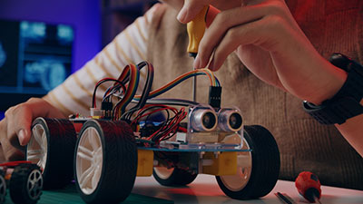
To spot the line, we require the measuring device, as stated in the block chart. Therefore, use double IR Sensors containing a photodetector and IR LED for line detection. We then place them together in a reflective approach. As a result, once they get into the reflective surface vicinity, they detect radiated IR LED brightness through a photodetector.
Next, within the Line Follower Robot, we need to configure the IR Sensor. The IR Devices have to be on the base alongside the black line.
Consistently, the Arduino UNO observes the two devices' records, hence turning as directed by the mark. Detecting the dark line first shows the robot has to move forward because there is a curve upfront. Then, the Arduino UNO will correspondingly send indications to the generator driver. The left motor runs slowly, allowing the robot to turn left, rotate reversely, or stop fully. Whiles else, the right-hand motor runs at a standard rapidity. In addition, by PWM, the robot reduces the rapidity allowing the motor terminal on the right hand to move right. 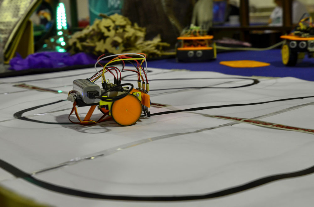
A small robot equipped with sensors
Note;
- You can create a sensor array recognition mark by LDR and LED pair.
- Once you use dual sensors (like our project), sensor position is vital. When placing the sensors, the thickness of black plays a significant role.
- Add the number of sensors to enhance dark mark recognition effectiveness. An assortment of devices escalates the accuracy, unlike when using just two sensors.
Programmable four wheels robotic car with line follow ability
Special Offer: Get $100 off your order!
Email [email protected] to get started!
Line Follower Robot using Microcontroller
The circuit connections feature L298N Motor Driver Unit, IR Devices, and Robot Framework containing a battery holder, four motors, and four wheels. In addition, the circuit connection features an 8051 microcontroller, which is the main component. The line follower robot requires an automatic chassis procedure. The IR onboard comprises an IR receiver and an IR transmitter. Once the car passes within the dark line, the black surface consistently absorbs the IR rays. Besides, it makes the analog output high since no rays are reflected. Every time the robot body passes outside the lighter surface, it reflects the IR rays, resulting in low output. Therefore, the sensor microcontroller signals the change of direction to the dual serial motor controller depending on the IR output.
Raspberry Pi Line Following Robot
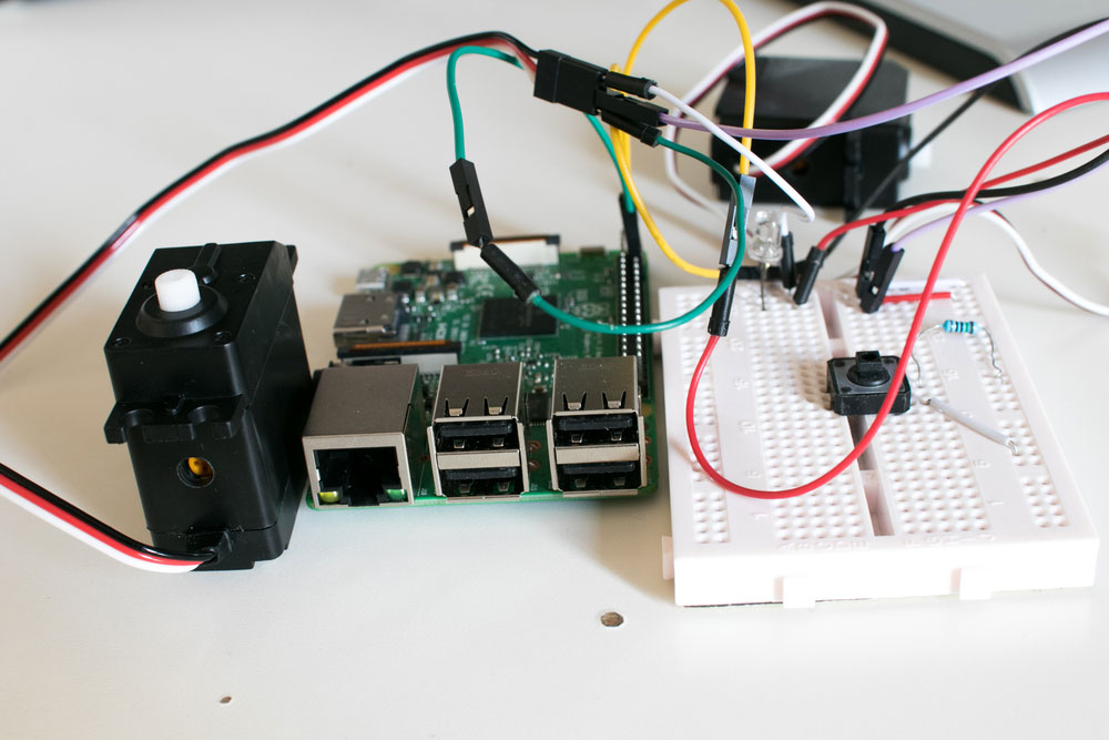
Making the robot trail within the line requires 2 IR devices positioned on the mark side by side. Raspberry Pi works as the “brain” as it's situated at the center of the robot. Through the DC motor driver, it accepts data from the two sensors, hence issuing control terms to accomplish the anticipated movements. Raspberry Pi GPIO pins can only have 5V voltage regulator output on maximum; thus, you need motor driver pins.
How Does an IR Line Following Robot work?
The IR sensor features a photodiode (IR receiver) and IR LED (IR transmitter). The transmitter will display infrared light while the receiver will wait to accept the light. The lighter color surface reflects the IR light normally. Nevertheless, the receiver won't have any reflection because the black surface will take in the IR light. Therefore, you can use an IR sensor that differentiates the black surface from the white surface. For instance, the moment when the infrared sensor is either on or off the line.
You need to palace two IR sensors side by side to follow the line. Ultimately, the robot will move straight once the two IR sensors aren’t on the line. Nevertheless, once one sensor isn’t in line and the other one is, you are notifying the robot to move toward the first sensor. Therefore, to ensure the robot remains on the line, it has to move left. Essentially, it makes the left IR device sense the mark while the right fails to detect it and vice versa.
Applications of Line Follower Robot
- Guidance application
- Automobile
- Industrial & defense application
Summary
Line follower robots can autonomously follow a straight pathway. As a result, you can use it in different automation processes in consumer, military, and industrial applications. Besides, its extra features such as security measures and obstacle avoidance make it appropriate for driverless cars.
Special Offer: Get $100 off your order!
Email [email protected] to get started!


