OurPCB specializes in Printed Circuit Board Assembly (PCBA), utilizing advanced technologies such as Surface Mount Technology (SMT). SMT allows for the efficient placement of smaller SMT electronic components directly onto the PCB surface, leading to reduced size and weight of the final product. By combining expertise in PCBA with the benefits of SMT, OurPCB ensures high-quality, reliable assemblies tailored to meet your electronic needs.
PCB assembly involves two technologies for mounting and soldering the components on the bare board: Surface Mount Technology (SMT) and Through-Hole Technology (THT). Most PCB manufacturers and assemblers use the former to build and assemble modern compact PCBs. Sometimes an SMT assembler will even combine both because SMT helps reduce the size and weight of the board.
So, what is an SMT exactly? Let’s analyze this technology in detail to understand its components, manufacturing process, applications, best practices, benefits, and how it compares to THT.
Contents
- What is Surface Mount Technology?
- Different Types of Surface Mount Technology
- What are the Common Components Used in SMT?
- Resistors and Capacitors
- Integrated Circuits (ICs)
- Diodes and Transistors
- Inductors and Transformers
- Connectors and Switches
- The SMT Manufacturing Process
- 1. Solder Paste Printing
- 2. Component Placement
- 3. Reflow Soldering
- 4. Inspection
- 5. Testing
- Applications of Surface Mount Technology
- Consumer Electronics
- Medical Devices
- Automotive Industry
- Aerospace and Defense
- SMT Principles and Best Practices
- Design for Manufacturing (DFM)
- Solder Paste Management
- Component Placement Accuracy
- Thermal Profiling
- Why is SMT Important in Electronics Manufacturing?
- Advantages of Surface Mount Technology
- Size and Weight Reduction
- Improved Performance
- Cost Efficiency
- Simplified Assembly Process
- What Challenges are Associated with SMT?
- Solder Paste Control
- Accurate Component Placement
- Thermal Profile Management
- How is SMT Different from Traditional THT?
- Higher Component Density
- Efficient Use of PCB Space
- No Drilling Required
- How Does SMT Compare to THT?
- Component Size
- Assembly Process
- Mechanical Strength
- Experience the Benefits of SMT
- Surface Mount Technology FAQs
- Is SMT Suitable for Prototyping?
- What is an SMD?
- What is the Difference Between SMT and SMD?
- Can You Combine SMT with THT?
What is Surface Mount Technology?
Let’s get into what is SMT technology all about!
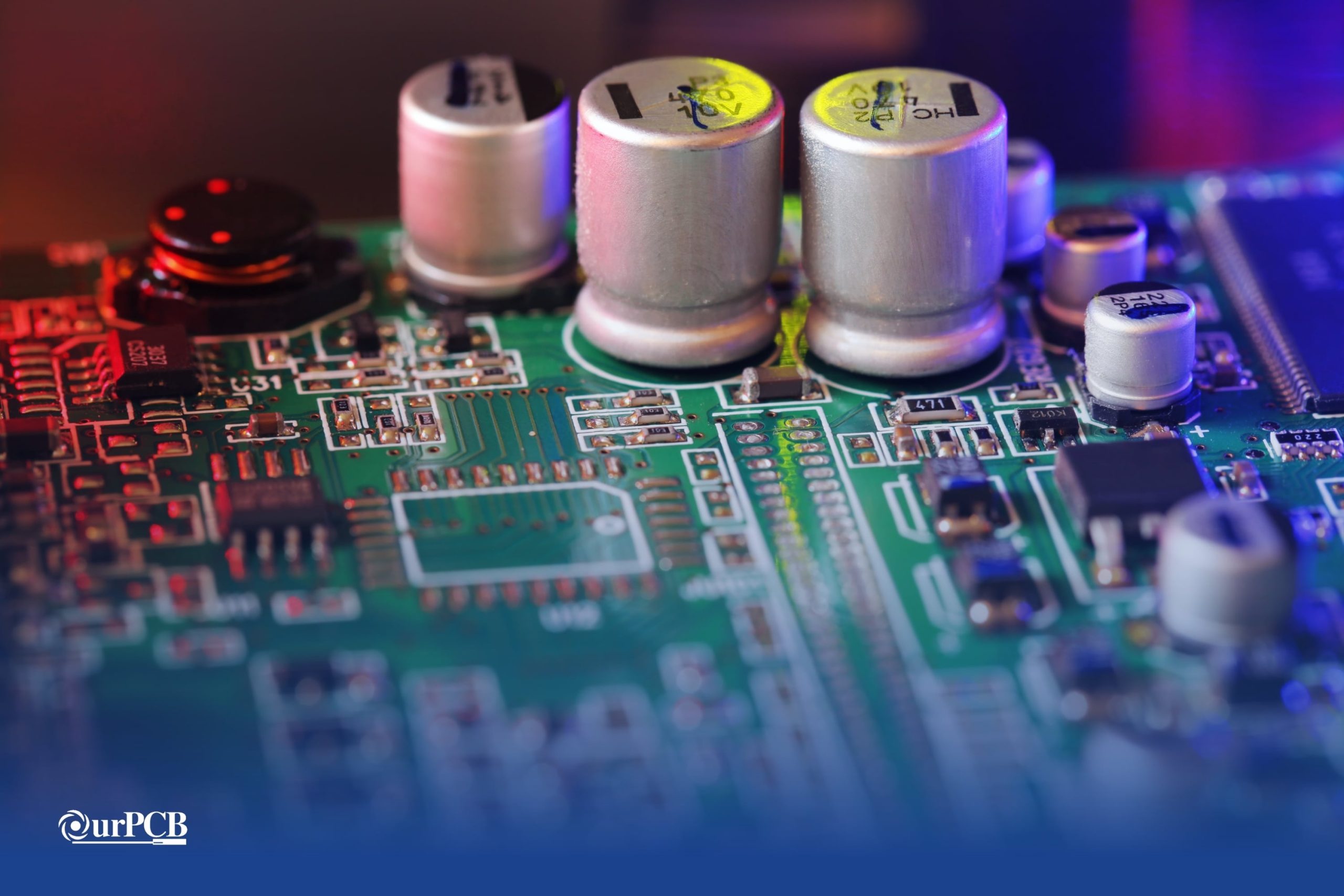
SMT (Surface Mount Technology) is a PCB production or assembly method that involves placing and soldering electronic components directly onto the PCB surface. The process requires a solder paste printer to apply the solder paste, a pick-and-place SMT machine for component placement, and a reflow oven to melt the solder and weld components to pads.
Different Types of Surface Mount Technology
There are three main types of SMT. Let’s get into the different types and how they compare.
| SMT Type | Description |
|---|---|
| Type I | This SMT type has surface-mount devices (SMDs) only mounted on one or both sides of the SMT board. |
| Type II | Type II SMT boards combine THT (aka, Thru-Hole Technology) and SMT components, with the active surface-mount components and DIPs located on the PCB’s primary side. The secondary side often has a passive SMT chip or chips. This SMT type is the most common, but it is complex because it requires multiple soldering processes (reflow and wave). |
| Type III | Like type II, these assemblies have passive SMT chips on the secondary side. However, the primary side only has active DIPs. |
What are the Common Components Used in SMT?
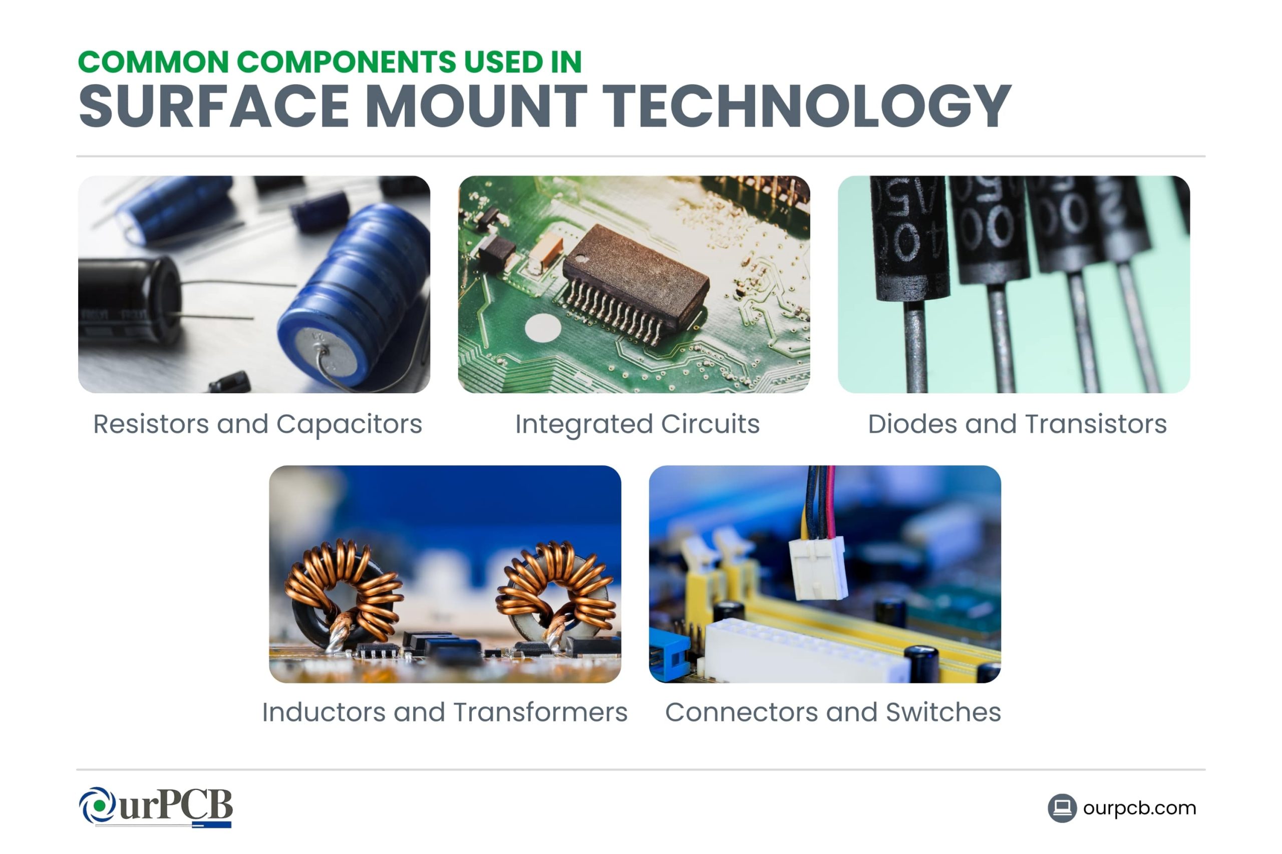 Resistors and Capacitors
Resistors are the most common SMD components, and their purpose is to limit the flow of electric current through the circuit. They include various types, such as thin film, thick film, wire-wound, and current-sense resistors.
On the other hand, capacitors store electric charge, functioning as temporary batteries or power supplies in the circuit. They include ceramic, electrolytic, film, and tantalum capacitors.
Integrated Circuits (ICs)
ICs are complex SMT components that have multiple transistors, resistors, diodes, capacitors, etc., on a single chip. They include digital, analog, mixed-signal, and power management ICs.
Diodes and Transistors
Diodes are 2-terminal semiconductors that only allow current to flow in one direction to help in rectification, signal processing, lighting, and voltage regulation. On the other hand, transistors are 3-terminal semiconductors that switch or amplify electric signals.
Inductors and Transformers
Inductors are single coils that store energy in a magnetic field when current flows through them. They are common in power supplies and analog circuits, where they stabilize the current flow and filter out high-frequency noise.
Transformers have at least two coils. They transfer energy from one circuit to another using magnetic induction.
Connectors and Switches
SMD connectors provide electrical connections between the PCB and external devices without permanent attachment (soldering). On the other hand, switches give manual control over the electrical current flow in a circuit.
The SMT Manufacturing Process
The primary steps in the SMT manufacturing process include:
1. Solder Paste Printing
SMT processing begins with solder paste printing. A solder paste printer uses a prepared metal stencil and squeegee or scraper to apply solder paste to the PCB surface at an angle ranging from 45° to 60°.
The stencil must match the circuit board and have the holes in the exact spots where the solder pads are located. Squeegees or scrapers spread the solder paste to cover the entire upper surface of the stencil so that the paste can penetrate through all the holes to reach the pads.
2. Component Placement
After solder paste printing, the next step is to place the surface mount devices on the pads above the printed paste.
A pick-and-place machine handles this process. It takes components from reel packages in the feeder and places them in the exact spot that matches the PCB layout diagram. It uses the pick-and-place file and component placement list to get the X-Y coordinates, rotation, reference designator, and other data required for accurate placement.
Placing SMT components manually is challenging, even when using tweezers because the pieces are tiny. Pick-and-place machines are more precise.
3. Reflow Soldering
The next step for the board in the conveyor line is to head to the reflow oven, which has these four zones.
- Preheat zone: This area preheats the board and all components to raise the temperature gradually at 1–2° C each second until it gets to 140–160° C. These temperatures evaporate solvents and activate the flux.
- Soak zone: Soaking means the board is kept at the 140–160° C temperature range for 60 to 90 seconds. The purpose of this zone is to deal with differences in thermal inertia because components don’t warm up at an even rate.
- Reflow zone: Soldering occurs in this zone, where the temperature gets ramped up gradually at 1–2° C each second until it gets to 210–230° C. This temperature is high enough to melt tin particles in the solder paste and make them wet both the component lead and pad. The surface tension of the molten solder keeps the components in place during this phase.
- Cooling zone: This zone lowers the temperature gradually at a maximum of 4° C per second to avoid thermal stress on the solder joints as they solidify.
4. Inspection
The assembled board undergoes cleaning and inspection to check for defects. Methods like AOI, X-ray, and visual inspection are common during these checks. If there are flaws, the board is reworked and inspected again.
5. Testing
The final step in the process is testing! Testing involves methods like flying probes, bed of nails, and solderability testing to ensure the PCBA is fully functional.
Applications of Surface Mount Technology
Consumer Electronics
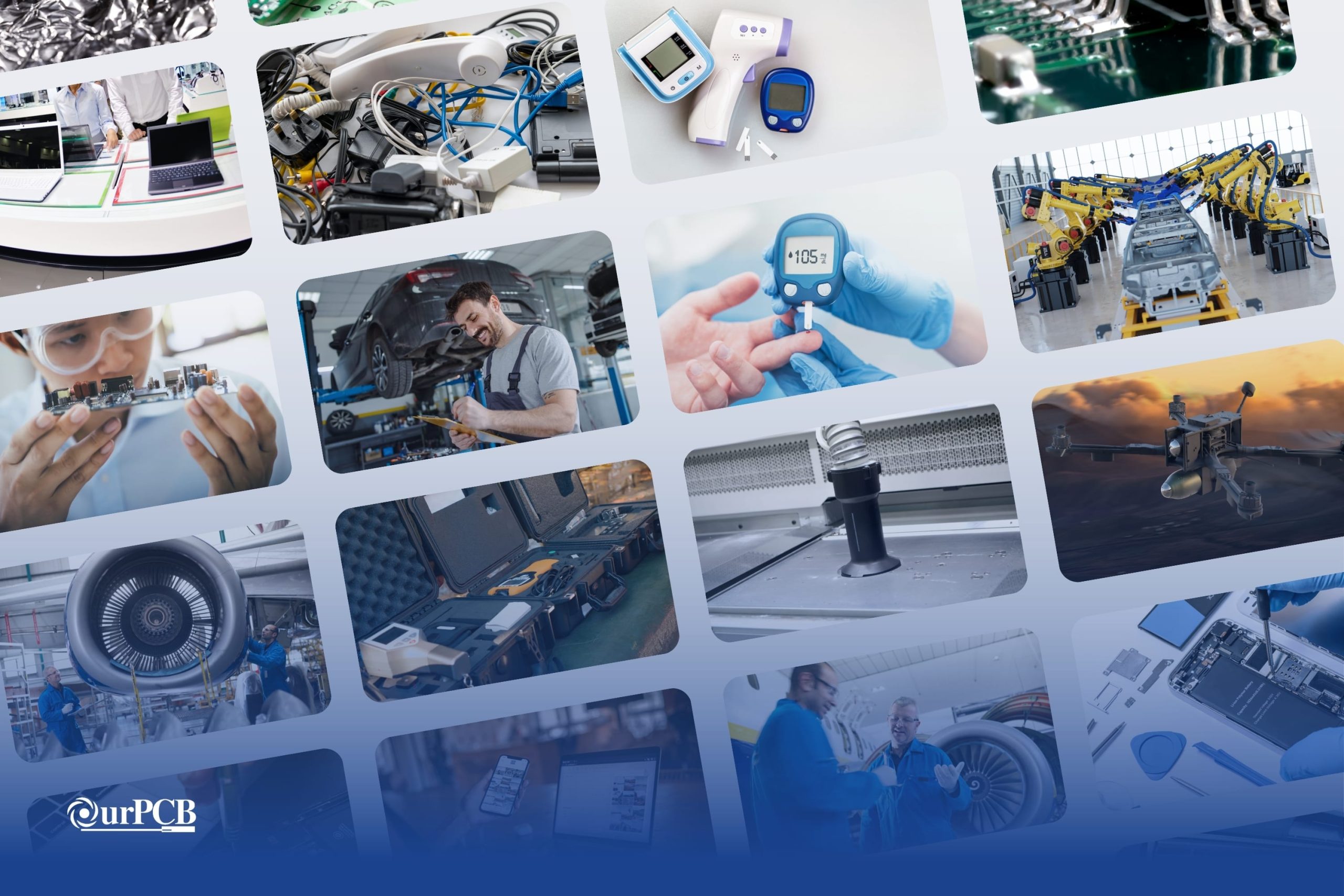
SMT is common in smartphones, laptops, smartwatches, and other compact consumer electronics because of its miniaturization advantage.
Medical Devices
Compact medical equipment like heart rate monitors, EMG, EEG, and ECG sensors, glucometers, and pacemakers require miniaturization, which is one of the benefits of SMT. The reliability offered by SMT is also important in medical devices.
Automotive Industry
Modern vehicles have several control systems and modules that require efficient, stable, and reliable operations. SMT provides these advantages.
Aerospace and Defense
SMT components can weigh up to 10 times less than THT devices, which results in high PCB weight reduction. This factor is important in aerospace and defense applications because lift pulls in the opposite direction of weight. Drones, planes, and rockets benefit immensely from this technology.
Special Offer: Get $100 off your order!
Email [email protected] to get started!
SMT Principles and Best Practices
When utilizing SMT, there are a couple of best practices to keep in mind. Remember these important rules and principles:
Design for Manufacturing (DFM)
DFM involves optimizing a product’s design to make it easier and cheaper to manufacture without compromising performance. In the case of PCBs, DFM optimizes the board’s layout to make the fabrication smooth while considering its SMT features (solder pads). The optimized layout also streamlines the SMT component assembly process.
Solder Paste Management
Solder paste should be stored at 0–10° C to increase its shelf life, with the cartridges positioned vertically (tip facing down).
Before use, let the paste warm to room temperature without forced heating. After that, shake the cartridge manually or with a centrifuge to mix the paste materials. Once open, use the paste within 2 weeks because it becomes less effective when exposed to air.
Solder paste printing is also critical. The stencil should be made of a strong material and have the correct thickness to avoid excessive solder deposition. Other factors like the stencil separation speed, squeegee speed, pressure, and angle are also important parameters.
Component Placement Accuracy
Pick-and-place machines handle SMT component placement, and they should be highly precise. Parts placed inaccurately might short-circuit, contact the wrong pad, or fail to contact the pad. Such issues require expensive and time-consuming reworking.
Thermal Profiling
This practice helps to determine the optimal temperature to set in the reflow oven’s heating zones to ensure the PCBs end up with high-quality soldered joints.
Why is SMT Important in Electronics Manufacturing?
SMT is important in electronics manufacturing because it:
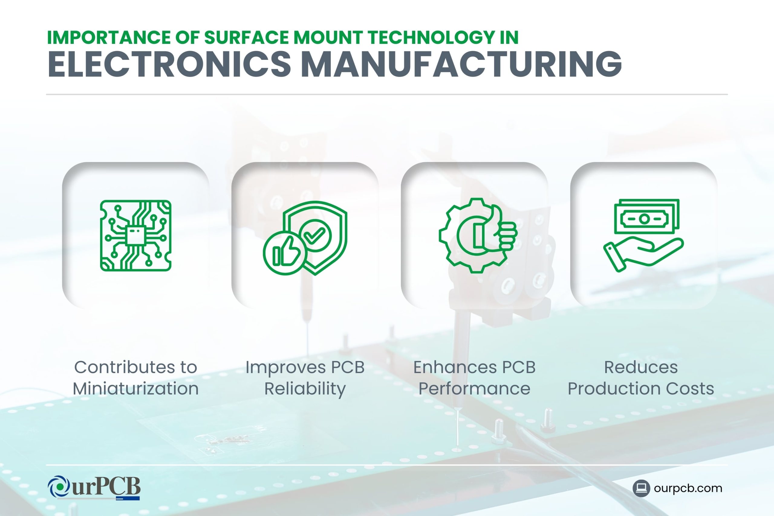
- Contributes to miniaturization
- Improves PCB reliability (less noise and parasitism)
- Enhances circuit board performance of PCBs (high component density)
- Reduces the production costs
These components are cheaper than their THT counterparts, and the assembly process is easier to automate.
Advantages of Surface Mount Technology
There are many benefits to using surface mounting in PCBs, from performance to affordability. These are the main advantages of SMT:
Size and Weight Reduction
Since SMT devices are smaller and weigh less, they enable miniaturization in devices like wearables, implantables, and smartphones.
Improved Performance
SMT is more reliable than THT because the SMT package and components have lower parasitic inductance and capacitance. Therefore, circuits with SMT assemblies have lower signal propagation delays and noise, especially as the frequency or clock speed increases.
Cost Efficiency
Since there is no drilling during manufacturing and the assembly process is easier to automate, SMT has lower production costs than THT.
Simplified Assembly Process
Not only does automation make SMT production more cost-effective, but it also simplifies the process and makes it more accurate.
What Challenges are Associated with SMT?
While SMT has many benefits, it still comes with its challenges. Here are a few potential issues to be aware of:
Solder Paste Control
Solder paste control is critical because excess deposition can lead to defects like:
- Tombstoning
- Solder bridging
- Short-circuiting
On the other hand, insufficient deposition can form weak solder joints or open circuits.
The challenges in solder paste control arise because of the required precision on various production variables, such as squeegee pressure, stencil alignment, squeegee angle, and stencil thickness. An irregular PCB surface and dirt can also affect solder paste control.
Accurate Component Placement
The tiny size of SMT components and their high density on the board’s surface make accurate placement challenging, but necessary to avoid defects.
Thermal Profile Management
Managing thermal profiles is also challenging because there is no single temperature point that works for all PCBs in the reflow oven zones. The heating zones usually have a 20° C range. Prototyping can help determine the optimum temperature for each zone and the variable for the gradual cooling process.
How is SMT Different from Traditional THT?
Both THT and SMT are technologies used to mount and solder components on a bare board. Here is how SMT is different from the traditional THT:
Higher Component Density
SMT components are significantly smaller than their THT counterparts, so it is possible to pack them at a higher density per unit area on the board’s surface.
Efficient Use of PCB Space
Because they are smaller than THT components, SMT parts occupy less space on the board. This makes it possible to build smaller PCBs or leave more space for other functions.
No Drilling Required
THT creates electrical connections between the board and components by mounting component leads into holes drilled through the PCB. These leads are soldered on the other side of the plated-through hole to create a reliable mechanical and electrical joint.
However, SMT involves mounting components directly on the PCB surface, which requires no drilling.
How Does SMT Compare to THT?
So, which one technology do you choose for your PCB? Here’s how SMT compares to THT:
Component Size
SMT components are significantly smaller than THT parts, primarily because they have smaller/shorter leads or contact pads. THT devices have larger and longer leads.
Assembly Process
Assembling SMT components requires solder paste printing, component placement using a pick-and-place machine, and reflow soldering. But THT assembly needs component insertion machines followed by wave soldering.
Mechanical Strength
THT provides more robust mechanical bonds with the board because the component pins go through the PCB and are soldered on the other side. These solder joints handle environmental and mechanical stresses better than SMT joints.
Experience the Benefits of SMT
Reduced weight, tiny size, higher electrical reliability, and automated production are some of the major selling points of SMT that have made it an attractive option in several industries. Although the technology has its challenges, its benefits far outweigh any drawbacks.
However, THT is also necessary for some components or PCB parts, so type II SMT is the most popular assembly in the electronics industry. But regardless of the type you want, we have the expertise and SMT equipment to fabricate and assemble the board for you. Contact OurPCB with your details and Gerber files, and we’ll give you a free pcb quote for your SMT-assembled board.
Surface Mount Technology FAQs
Is SMT Suitable for Prototyping?
SMT is challenging for prototyping because steps like solder paste printing and component placement need stencils and pick-and-place files for specific board designs. Consequently, prototyping can be costly, but it is doable.
What is an SMD?
An SMD is a Surface Mount Device. An SMD device is mounted on a PCB utilizing surface mount technologies. SMD electronics are designed to not have components with leads that go through holes, as they are soldered onto pads on the surface. SMD parts include resistors, capacitors, and an SMD chip.
What is the Difference Between SMT and SMD?
SMT is the surface mounting process in this PCB assembly technology, while SMD refers to the component or type of device used.
Can You Combine SMT with THT?
Yes, type II SMT combines SMT with THT, which are even on the same side of the board.
Back to top: Surface Mount Technology (SMT)
Special Offer: Get $100 off your order!
Email [email protected] to get started!


