Haptics is a broad field because it encompasses any technique that stimulates the touch sensation. And most innovations that have touch screens feature vibration haptic feedback to indicate the registration of an action. Haptic motors are the devices used to provide these vibrations. Here's a close analysis of these devices and the typical types used in mobile devices. We will also explain how you can use an Arduino board to control the haptic motor driver. Read on to learn more!
Contents
What is a Haptic Motor?
A haptic motor is a device that adds tactile feedback to electronic devices by using vibrations. These vibrations provide a deeply enhanced user experience in portable, handheld touchscreen devices, such as smartphones, game controllers, wearables, medical devices, etc.

A haptic motor for a smartphone
Special Offer: Get $100 off your order!
Email [email protected] to get started!
Haptic Motor Drive Mechanism
The drive mechanism of a haptic or vibration motor consists of four devices.
First is the touchscreen or capacitive buttons. This component senses the touch event and sends a trigger signal to the processor.
The second component is the processor. It can be an MCU (Micro Controller Unit) or an applications processor. The processor receives the trigger from the touch/press event, then generates a waveform (digital or analog signal).

A virtual reality headset with haptic feedback
A driver forms the third component. It receives the waveform from the processor to drive the actuator.
Lastly, the actuator or haptic motor moves in a specific pattern or direction to match the electrical signal it receives from the driver. This movement causes a vibration that creates haptic feedback on the screen.
Typical Haptic Actuator Types in Mobile Devices
The three primary haptic actuator types include the following.
Eccentric Rotating Mass (ERM)
ERMs are magnetic motors that use an unbalanced mass to create vibrations and come in two types.
- Coin vibration motors
- Cylindrical vibration motors
These are the oldest and most mature haptic technology in commercial terms. And they are available in a wide range of performance and power specs. However, they are slow to start up and shut down because of the mass inertia. They take about 40-100 ms.

A mobile vibration motor with an unbalanced mass
The motor's frequency/speed determines its output amplitude/strength. So it is challenging to generate subtle or complex waveforms.
Pros
- Mature technology
- Affordable
- Simple to use
- Widely available
Cons
- Slow start-up
- Output strength depends on the frequency
- High power consumption
Linear Resonant Actuator (LRA)
These tactile actuators feature a magnetic coil that pushes a mass up and down to create vibrotactile feedback. LRA vibration motors have a similar form factor to their ERM counterparts but generate linear motion that feels cleaner and more direct.

A phone vibrator motor
Although the LRA motor's strength or amplitude is more flexible, its resonance mechanism operates on a narrow frequency range. But it has a low driving voltage (about 2V), making control easy using standard components.
Pros
- Generates direct linear motion
- Flexible strength/amplitude
- Low driving voltage
Cons
- Narrow frequency range
- Costlier than ERM
Piezo Module
Piezo modules or benders contain two types of piezoelectric material mounted as a cantilever beam configuration. After applying a voltage signal, the beam bends and creates significant motion at the beam tip.
Think of the motion created by a diver jumping on the diving board. This bending motion is the actuator's displacement, deflection, or strength.
The piezo base material used for these actuators is usually PZT, a class of ceramics that is brittle in its raw form.

A game controller with a haptic motor
Pros
Piezo modules have one primary advantage; a quick response time of about 1 ms. Aside from that, you can set and hold it in position because the actuator's deflection is directly proportional to the voltage of the control signal.
Also, you can independently control the deflection frequency and amplitude/position, which is impossible with LRA and ERM. So you can create more detailed and complex signals.
Despite this level of control, the benders have a lower current consumption than the other two types of motors (for a similar output). And this power consumption is a significant factor considering the device's overall power consumption because it is in the order of 0.1W to 1W.
And because they have a wide amplitude and speed range, these modules run effectively at the power range's lower end.

A phone vibrator motor. Note its tiny size compared to human fingers
Cons
These benders require a high driving signal voltage of around 200V. So they need piezo driver integrated circuits to amplify 3.3V or 5V to 200V.
Also, the motor driver circuits are complex and have long been a barrier that limits the actuator's accessibility.
Comparison
| Variable | ERM | LRA | Piezo Module |
| Form Factor | Hockey puck or bar | The Hockey puck | Hockey puck or bar |
| Dimensions | 11 x 4.5mm | 10 x 3.6mm | 3.5 x 3.5 x 42mm |
| Durability | Varies | Durable | Durable |
| Sensation Fidelity | Low | Medium | High |
| Voltage | 1-10V DC | 2.5-10V DC | 50-200V PP |
| Power | 10% of the battery | 5% of the battery | 7% of battery |
| Frequency | 1-300 Hz | 170-180 Hz | 0-500 Hz |
| Response | 40-100 ms | 20-30 ms | 1 ms |
| Waveform | DC voltage | Sine wave | Sine wave |
| Control | DC | Amp. Mod | Large BW |
| Power consumption (current) | Poor | Good | Best |
| Cost | $ | $$ | $$$ |

ERM mobile vibration motors
Haptic Motor PWM and On/Off Tests Using Arduino
We will use a coin vibration motor for this project. It is a flat DC micromotor known as a pancake motor. You can buy a ready-to-use motor module from Texas Instruments, and it should have three pins: IN, VCC, and GND. These cheap modules have a single MOSFET in the circuit to control the motor using a logic-level input signal.
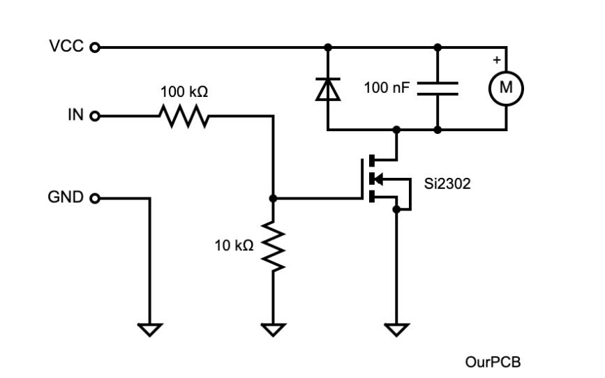
Alternatively, you can buy the individual motor and build the circuit using the following diagram.

A haptic motor MOSFET driver circuit diagram
If you cannot get the Si2302 SMD MOSFET, replace it with regular logic-level MOSFETs like IRLZ44 and IRL530. This component acts as a switch to turn the motor on or off. You switch an N-channel MOSFET to an on state when the applied voltage exceeds the gate's threshold voltage. So you switch it on by connecting a 5V input and off by setting it to low (0V).
Arduino Connection
Since it is a 5V motor, we will use Arduino UNO's regulated 5V DC output to power the motor's driver circuit. Connect the Arduino's D9 I/O pin to the driver's IN (signal pin) and supply power to the MOSFET driver using a 9V lithium-ion battery.
Open your Arduino IDE, write the following code, and upload it to the microcontroller.

This code is simple because it creates vibration effects or patterns based on time. Generally, vibrations get generated after meeting certain conditions. So you can expand this circuit further to include a touch sensor to get the input that triggers the haptic driver.
Wrap Up
There you have it! Vibration motors are vital in providing haptic feedback to electronic devices, and they primarily consist of three types. ERM actuators are the cheapest of the three types, and we have shown how to incorporate them into your project using Arduino. If you need help mounting these motors to your PCB, contact us, and we'll get you what you need.
Special Offer: Get $100 off your order!
Email [email protected] to get started!


