Do you need an appropriate gadget for measuring the level of sound intensity? Get yourself a Vu meter to help you realize the power of the sound going through your ears!
When a VU meter connects to a piece of audio equipment, it provides you with an opportunity to establish the strength of the sound waves.
This article illustrates the working of various meter circuits and the underlying mechanisms behind operating the gadgets. Make the correct decision of an appropriate VU meter after reading the article!
Contents
Purpose of a VU Meter
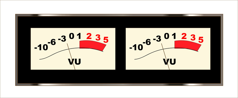
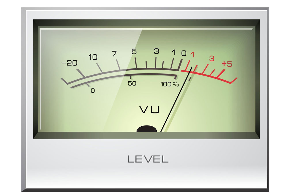
Voice unit meters feature dynamic characteristics used in measuring human ear responses to sound waves. VU meters operate sound recording and reproduction systems to evade overloading and noise distortion. Unique ballistics assists VU meters in calculating the power levels in audio frequencies. In the case of compound waves such as speech, the volume unit meters show the values of the average and peak of a complex wave. When you apply the waveform of a speech to the meter, the movement specifies valleys and mountains within the signal.
An Analog VU Meter
Special Offer: Get $100 off your order!
Email [email protected] to get started!
Types of VU Meter Circuits
The transistor version VU meter is one of the most popular, cheap, and easy-to-use VU meters. The strongest of all meters is the 20 to 40 type which reads sound powers of the most robust sound systems. Other types of circuits are the 5 LED VU Meter circuit, 10 LED meter circuit, VU Meter using DC voltmeter, and the peak reading VU meter by IC CA3130.
5 LED VU Meter Circuit
The VU meter has only a simple circuit with necessary parts only. Reminiscent with the old aged versions, the 5 LED meter circuit supports just sound waves of lower strength levels. However, the meter circuit is equally convenient.
Below is a diagram of a 5 LED VU Meter.
5 LED VU Meter Simple Circuit
Four diodes of the VU meter, i.e., D1 to D4 passes the input to the audio signal.
Three functions of the diodes include:
- Rectifying the audio signal.
- AC voltage to DC voltage.
- Dividing the audio signal to decrease respectively consistently.
The audio signal is forwarded to each transistor featuring Q1, Q2, Q3, and Q4 through resistors R5-R8. The voltage of each diode is 0.6V holding a sign of up to 1.8v. LED1 to LED4 displays the signal level, with LED1 showing the least light and LED4 indicating the most level signals. LED 1 to LED 3 signifies appropriate sound power to your ears, while LED4 and LED5 offer a high power level.
25 LEDs VU Meter Circuit (Increased LED)
The 25 LEDs VU meter circuit is an improved version of the previous LED5. The below diagram shows circuit transistors of double voltage capacity. Dual incoming AC reciprocates the same to the DC voltage. The addition of 25 LEDs enables the audio signal into more voltage. Therefore, the transistors drive every transistor to produce much more light. The version of the 25 LEDs circuit supports stronger sound waves than the 5 LEDs meter circuit.
25 LEDs VU Meter Circuit Diagram
20 to 40 LED Meter Circuit Schematic
If you want a 20 LED meter schematic circuit that drives LED up to 20 PCs, then purchase a 40 LED VU meter. The diagram below shows a perfect example of the 20 to 40 LED VU meter. An input signal from the power amplifier goes to VR1 to adjust the amplitude produced by the input signal to a proper level. Then circuits C1 to D2 signal to the voltage doubler rectifier circuit, and all transistors labeled Q1 to Q10. Additional transistors translate to more voltage-current input and higher power wave strength capacity. The meter circuit schematic features the strongest of all circuit transistors.
20 to 40 LEDs Meter Circuit Diagram
10 LED VU Meter Circuits
A 10 LED VU meter displays six signals when connected to an amplifier. A 24MV is enough to illuminate the highest signal indicator. The 10 LED VU meter circuits' high sensitivity fits any standard sound system. Hence known as an easy maximum level sound volume detector.
10 LEDs VU Meter Circuit 1
The above configuration only allows 0.12 V waves in the first LED lights, 0.24 for the second light, and 0.36 in the third lighting. The input signal of the gadget enables only sensitive modification of the circuit to the required intensity. A fine-tuned audio signal then is fed to a standard low emitter built around BJT Q1, which can hold ten times higher. Capacitor labeled C2 receives the output signal from Q1 and takes it to IC1. Resistor R5 acts as the input preference resistor for IC1, whereas D7 is the diode that guards Ic1 against extremely negative voltage. Lastly, the R6 resistor peddles current to each LED, restricting the current to around 12mA.
Nevertheless, IC1 can only work within half positive cycles, and hence, the LEDs only turn on 50% of the time. Consequently, the overall current remains 6MA for each LED. The potential current consumption of the LM3914 10 LED VU meters transistors accommodates not more than 8mA, which may go up to 44mA upon switching on all LEDs. You can get an improved circuit version of IC LM3915.
The difference between LM3915 and LM3914 is that the former displays positive voltage and after a negative voltage input. However, both are the same form, shape, and voltage: the figure below shows a simplified version of IC LM3915.
10 LEDs VU meter circuit 2
VU Meter using DC Voltmeter
Do you still feel like clinging to the use of 10-meter VU circuits without necessarily upgrading to 20 to 40 LED VU meters? Then purchase a volume meter circuit using direct current. The VU Meter circuit in the figure uses DC. In this case, the input music AC signal's amplification is first done, then put into proper levels and converted to direct current. The potential supporting the music level displays at the voltmeter connected circuit. As long as the VU meter connects with the early stages of the pre-amplification, it keeps an amplifier of any level, from audio mixer to any level music system.
In the absence of the input signal, the current intake of the movement is around 2.8mA. The sensitivity exhibited in the other ten led VU meter is dealt with by adjusting the 12k preset.
VU Meter using DC Voltmeter
Peak Reading VU Meter by IC CA3130
Peak reading is the oldest version among all the VU meter reading circuits. In this connection, the peak reading VU meter remains the easiest to operate with no technical knowledge. The performance is used in less sophisticated sound systems like microphones. You can also decide to make your own with a bit of training. You are just required to acquire the necessary locally available materials.
Peak Reading VU Meter by IC CA3130
Characteristics of VU Meters
The captivating faultiness and levelness ballistic response match the incomparable most OK hardware meters. The plugin emanating from the waves will help you establish appropriate gain designed to an expansive and pure mix. The outstanding characteristics of a VU meter include the following, rise time, reference level, impedance, and frequency response. All the four main features of a volume unit replicate in all the circuit types.

Analog VU Meter
Summary
VU meter gadgets are popularly known for measuring sound power. Each type of VU meter functions according to the strength of the circuits. Amplifiers relating to various sound stems produce such current commensurate with the strength of a sound system. Therefore before connecting an amplifier to the VU meter, you should consider the underlying circuits supporting the operations system of the VU meter. If you need the discrete components to make a VU meter circuit, or you want a complete PCB assembly, contact us for more details.
Special Offer: Get $100 off your order!
Email [email protected] to get started!


