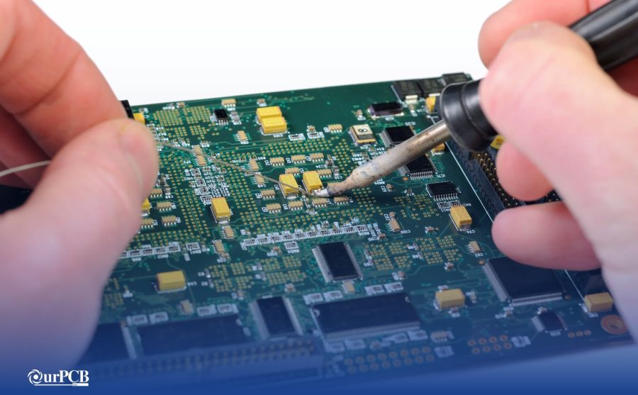
Nowadays, many devices operate on smart sensor technology. And because they often use analog output, these devices need an analog-to-digital converter.
However, there are not many better options than the MCP3008 pinout.
Unlike the Raspberry Pi, the MCP3008 chip has hardware SPI support that reads analog input. Also, it is affordable compared to other development tools.
At the same time, it gives you optimum designs. Going further, you learn where to use this logic-level microchip and how to get the best out of it.
Contents
MCP3008 Pin Configuration
Here is a configuration of the MCP3008 pinout alongside the names and descriptions of each pin.
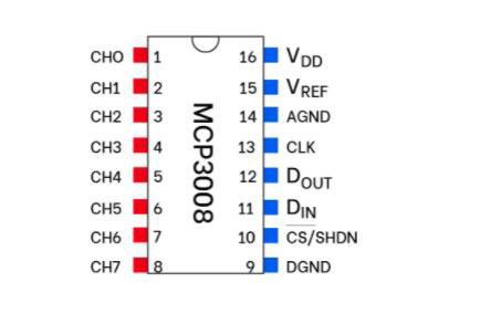
Source: Wikicommons
(Pinout of MCP3008 illustrated)
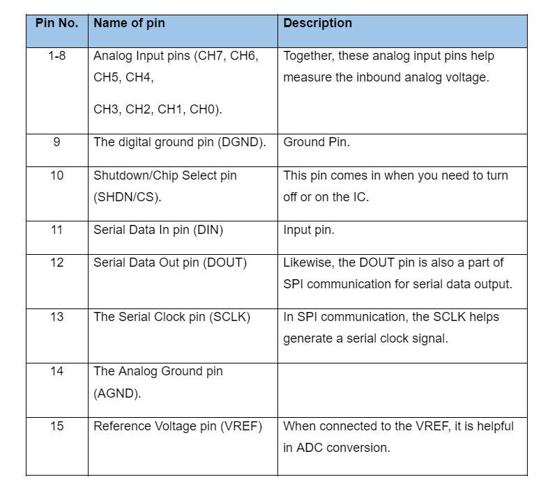
Features and Specifications
Below are some features and specs of the mcp3008 pinout.
- Firstly, it is an 8-channel 10-Bit ADC IC.
- Also, its communication protocol is via an SPI interface.
- The operating voltage ranges from 2.7V to 5V.
- On the other hand, the sampling rate for 75 ksps and 200 ksps are 2.7V and 5V, respectively.
- Further, it uses successive approximations as its ADC method.
- Usually, the standard packages are the 16-pin PDIP, SOIC, and TSSOP.
- The MCP3008 pinout has programmable analog inputs.
- Also, it has a sample-and-hold feature for on-chip operations.
- The IC runs on CMOS technology and uses low power.
- Further, it uses a standby current of 5nA and a max of 2 µA.
- Meanwhile, at 5V, its maximum active current is 500 µA.
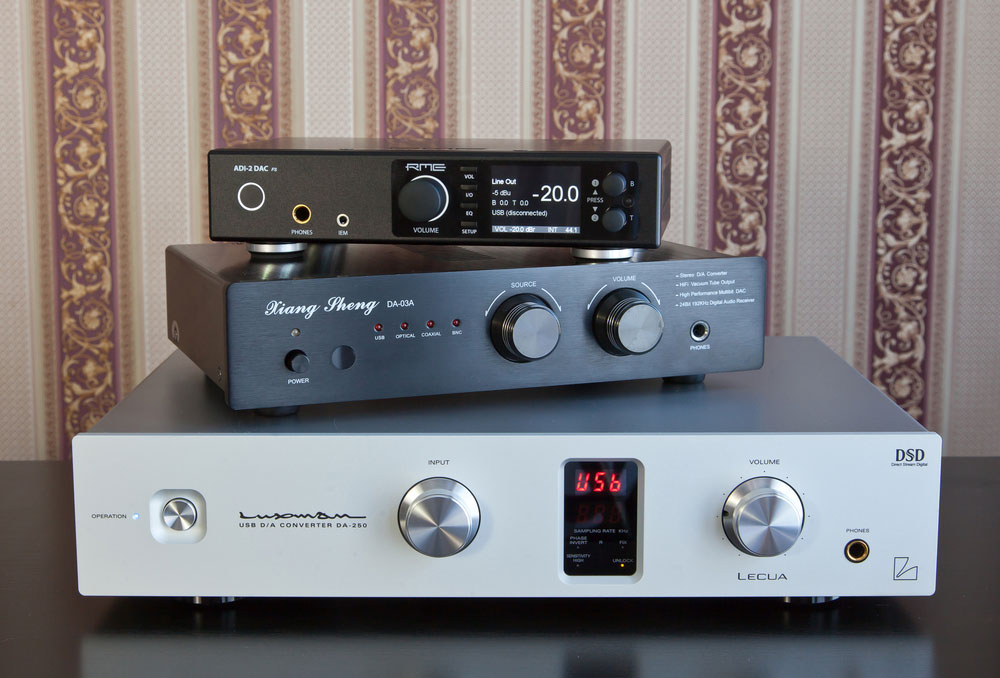
(A pile of ADC and DAC machines).
MCP3008 Equivalent
- PCF8591
Special Offer: Get $100 off your order!
Email [email protected] to get started!
Alternatives ADC ICS
However, there are a couple of alternatives for the MCP3008 IC. They include:
- ADC0804
- ADC0808
- ADS11115
Where to use MCP3008?
Typically, when the IC measures analog voltage value, it sends it to an MCU via SPI communication.
Therefore, you use the MCP3008 pinout with microcontrollers that operate on 3.3V or 5V. Often, these systems include the Raspberry Pi, etc.
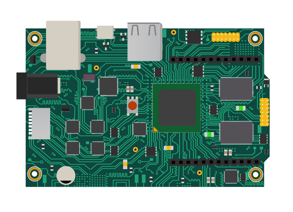
(A logic-level Raspberry Pi board).
How to use the MCP3008 pinout?
First, set the ADC in an optimum operating voltage range of 2.7V - 5V. Note that the reference voltage must never exceed the operating voltage.
Otherwise, match the VREF to 5V in line with the VCC pin.
Typically, channel 0 up to channel seven helps supply analog voltage for measurement purposes.
As a result, each analog input channel pin gives a 10-bit resolution with the reference voltage and the maximum voltage.
In other words, an input voltage ranging between 0V and 5V yields 0-1023 digital data.
After measuring analog voltage, the microprocessor helps you obtain the value via SPI communication.
To achieve this, you need to connect the Clock pin, Din, Dout, and CS pin to the SPI pins of the MCU.
(A satellite dish for converting analog-digital signals).
7. MCP3008 Pinout Applications
Among the numerous applications involving the MCP3008 pinout, the most common ones are below.
- The IC is a crucial part of analog sensor interfaces.
- Also, it helps in data acquisition and conversion.
- The IC is useful in process control.
- It is also essential in battery-operated devices.
- Further, it is applicable in use with ADC module extensions.
- It is helpful in applications involving Microprocessor development boards like Arduino Uno or Raspberry Pi.
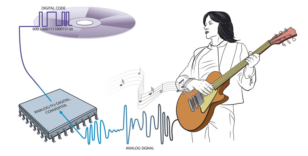
(An illustration of an ADC converting analog to digital signals).
Conclusion
In brief, the MCP3008 pinout is a 10-bit programmable ADC converter with eight input channels.
As a result, it is essential in applications that involve embedded systems.
So, starting a project with the MCP3008 pinout, you may need additional resources.
Therefore, if you decide to experiment and need assistance, feel free to contact us.
Special Offer: Get $100 off your order!
Email [email protected] to get started!


