Blog  /  IC Packaging: What Is It and Why You Need It for Your Electronic Devices?

IC Packaging: What Is It and Why You Need It for Your Electronic Devices?

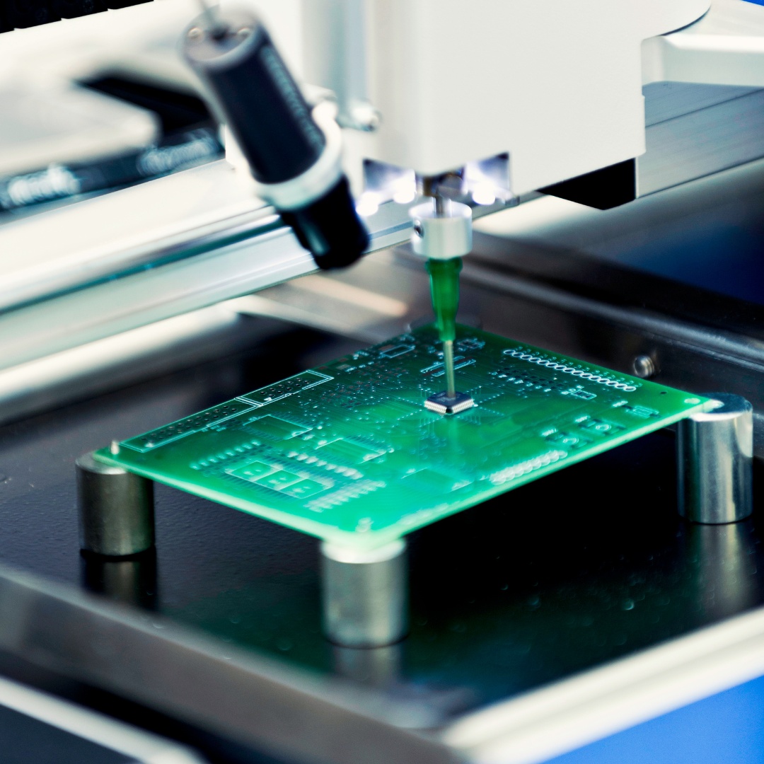
IC packaging plays a vital role in protecting semiconductors and ensuring their longevity. At OurPCB, we specialise in PCBA (Printed Circuit Board Assembly), which includes the careful integration of IC packaging to safeguard your electronic components. Our expertise ensures that your devices remain reliable and functional over time, meeting the demands of modern technology.
Quote Form
check whiteFast Turnaround check whiteISO Certified
1 2 3

When you see the word; IC packaging, what’s the first thing that comes to mind?

Of course, protection. Or perhaps security. Whatever word you choose is acceptable. And it’s because IC packaging enables semiconductors to last longer.

If you’re an engineer, you should know about them. And it would help if you were using them to make your semiconductor work for many years without developing faults.

It’s okay if you don’t know about IC packaging. We’d be talking extensively about it later in this post.

But how does it work?

IC packaging makes every chip in a PCB board to stay protected from possible stress and the elements.

So, are you ready for some in-depth knowledge about IC packaging? Then, let’s jump into the article.


1. What Is IC Packaging?


We’ll define IC packaging, also known as integrated circuit packaging, in simple terms.

So, it refers to any component that has a semiconductor device. And the package is an encasement that surrounds the circuit device. Plus, its primary purpose is to prevent the device from:

  • Physical impairment
  • Corrosion

But that’s not all.

It also serves as a platform that allows electrical contacts mounted on it to connect to the PCB.

When it comes to IC packaging, there are different options to consider. And it’s because of the various circuits available. Also, these circuits have other requirements due to their outer shell.


What Stage is the IC Packaging Essential?


Typically, IC packaging is the last production stage of semiconductor devices. Hence, at this stage, the semiconductor component gets protected in an enclosure. And this enclosure package does one thing. It shields the IC from possibly damaging the external elements. Plus, it also protects it from corrosion.

So, here’s the deal.

The enclosure package is an encasement. It’s responsible for protecting the device block. And it also helps to promote vital components. One of such is the electrical contacts. These components help to carry signals to the PCB of an electronic appliance.


The History of IC Packaging


Since the 1970s, IC packaging technology has experienced steady growth. Initially, they started as a ball grid array (BGA) package. And most electronics manufacturers used it as well.

But later, at the beginning of the 21st century, newer varieties overtook the pin-grid array packages.

They called the new varieties:

  • Plastic quad flat pack
  • The thin small outline package

As time passed, a few manufactures like Intel brought land grid array packages into existence.

In the interim, flip-chip ball grid arrays (FCBGAs) surpassed BGAs. And it’s because of the FCBGAs house more pins than other package designs.

Also, the FCBGA has input and output signals above the complete die, contrary to the edges.


2. The Different Types of IC Packaging


There are about ten different IC packaging types. But in this article, we’ll list four.


2.1 Through-Hole Mount Packages


Hole Mount Packages


This IC packaging is a mounting structure used for electronic parts. And they include the use of lead (Pb) on the parts that insert into the PCB’s drilled holes.

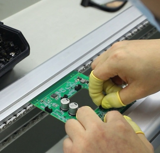
They also get bonded to pads on the reverse side. And this happens by using mechanized insertion mount machines. Or by using manual assembly, which is hand placement.

The Through-hole mount packaging is ideal for parts that aren’t suitable for surface mounting. An example of such is heatsinked power semiconductors and large transformers.


2.2 Surface Mount Packaging


Surface Mount Packaging


The surface mount IC packaging refers to a method where electrical components are mounted directly on the PCB’s exterior.

Any electric device that uses this method of IC packaging is a surface-mount device (SMD).

Also, the advent of the Surface mount packaging technology swallowed up the Through-hole mount packaging.

Why was this so?

It was because SMT supported increased automated manufacturing. And it enables quality improvement and cost reduction.

But that’s not all.

The surface-mount packaging has a platform that allows more components to get fitted to a specific area.

Also, when compared to through-hole mounts, SMT is smaller. And it’s because it has got smaller or no leads. Plus, it has the following:

  • Flat contacts
  • A lead of various styles or short pins
  • Terminations on the component’s exterior
  • A matrix of solder balls


2.3 Chip-Scale Packages


Another name for the Chip-Scale packages is chip-size packaging. It derived that name because it’s one of the few packages that come in chip size.

But that’s not all.

For an IC package to be qualified as a chip-scale, it must meet these criteria:

  • Be a single-die
  • Have a direct surface mountable package
  • Have an area that’s lesser than 1.2 times the size of a die

In 1993, Gen Murakami of Hitachi Cable and Junichi Kasai of Fujitsu proposed the above concept. However, Mitsubishi Electric created the first concept demo.

But there’s more.

The chip-scale technology requires the following:

First, the interposer where balls or pads get formed must hold the die. And this packaging is similar to the technology of the flip-chip ball grid array packaging.

Second, the pads may be printed or etched directly into the silicon wafer. And this results in a packaging that almost has the size of the silicon die. A perfect example of such packaging is a water-level chip-scale package (WL-CSP) or a water-level package (WLP).

In the 1990s, the production of WL-CSP started. But a lot of companies began mass-producing it at the beginning of the 2000s. Advanced Semiconductor Engineering is an excellent example of a company that mass-produced the WL-CSP.


2.4 Ball Grid Array


Ball Grid Array


Ball grid array is a type of packaging used to mount microprocessors permanently.

But that’s not all.

The package also provides more interconnection pins than a flat or dual in-line package.

Hence, the best part of this package is:

You can use the entire bottom surface, not only the perimeter. And the traces joining to the package leads to the balls or wires.

There’s more.

These balls or wires connect the die to averagely shorter packages, which are perimeter-only. In the end, the package brings about higher speed and better performance.

Also, as an engineer, you need precise control to solder BGA devices. And it’s because of its very delicate system. Thus, most companies stick to automated processes to avoid errors.


3. What Are the Required Materials for IC Packages and the Mode of Assembly


The required materials used to build different IC packages are essential.

Why?

It’s because three factors establish the foundation of a package. And they are:

  • Chemical properties
  • Physical properties
  • Electrical properties

But that’s not all.

The performance of the package also acts as a limiting factor.

So, let’s dive into the three primary package materials.


3.1 For Leadframe Materials


The lead frame materials are the dominant IC package materials. Hence, engineers use them mostly for wire-bondable finishes and wire-bond interconnected die. And a perfect example is gold or silver.

These finishes get plated in the inner bond-land area via a spot-plating method. By doing so, you’ll be saving a ton of cost. And it’s because noble metals don’t join to encapsulants with ease.


3.2 For Ceramic Packages


Inconel or Alloy 42 is a common choice for ceramic packages. Why? It’s because there’s a linkage between the alloys and CTE. The close match is a crucial feature because of the ceramic’s brittleness.

But, the low CTE could have a harmful effect. And it’s worse if you install the final assemblage of surface mounted devices. However, the size of the CTE plays a significant role. And we can link everything to the mismatch of most common PCB substrates.

We must also note that lower CTE metals have an excellent reputation to work well as lead frames. And they work perfectly for plastic DIP-type and ceramic packages.

However, copper lead frame materials are usually an ideal choice for surface mount plastic packages. And it’s because they have the capacity and compliance to secure solder joints.

But that’s not all.

Copper also has a higher conductivity, which is a great plus.


3.3 Laminate Materials


For IC packaging, you can substitute lead frames for laminate materials. And they come in handy when you have high I/O counts. Or perhaps you’re looking for high-performance levels.

But here’s what you should know.

Since the late 1970s, laminates have been in existence. And then, they used them for chip-on-board systems. Hence, if you take a good look at chip-on-board, you’d notice something. It comes with all the necessary elements required in a package.

Plus, it has a package situated in the original place.

Asides from that, laminate packages serve as cost-effective options. It’s even more affordable than the thin and thick ceramic substrates. Thus, most engineers widely use it because of its economic value.

Also, engineers prefer newer organic laminates with higher temperatures. And it’s not only because it’s cost-effective. But they have more preferred electrical attributes. A great example is the lower dielectric constant.


Special Offer: Get $100 off your order!

Enjoy $100 off your order! No hidden fees and no minimum order quantity required.
Email [email protected] to get started!

4. Die-Attach Materials


Die-attach materials are excellent for bonding die to the substrate. The process may seem easy at first, but it has various requirements. And it depends on the application.

However, most times, the die attach is ideal for face-up-wire-bond assembling. So, it’s thermally conductive. But in some cases, it’s electrically conductive.

Also, the die-attach process must have no vacuums in the attached material. That way, you can avoid hot spots on the die. And as the chip-power of the die-attach material rises, it gets more value.


5. Encapsulants


An encapsulant is more like the final piece of an IC package. Hence, it has a primary function of protection. And the encapsulants protect the delicate bond wires and chip from the environment and physical damage.

So, you need to apply it with precision and care. That way, you’ll prevent wire sweep, which may cause shorting wires to one another.

But that’s not all.

When it comes to IC packaging, there are three basic types of encapsulant materials that are useful:


5.1 Epoxy and Epoxy blends


Epoxy and epoxy blend is quite popular among manufacturers. After all, organic resins are the most common in structural-engineering applications. Plus, it’s a beneficial mix of thermal performance and properties at a low price.


5.2 Silicone Materials


Silicone materials are the second most popular encapsulants. And they come in handy for IC chips. No doubt, the processing and curing regimens of silicon materials are similar to organic resins.

But, this material is not an organic resin.

There are two basic types of silicone resins:

  • Room temperature-vulcanizable (RTV)
  • Solvent-based

You can also achieve curing (converting silicone to solid) with different mechanisms. And it depends on the type of silicone material you choose.

As for the room-temperature-vulcanizable, you can cure it either by:

  • Catalyst addition
  • Exposure to moisture (room humidity)

On the other hand, the most common way you can cure solvent-based resins is by thermal means. But, you can only fix the solvent-based resins after evaporation of the solvent.

Silicone resins are a popular choice for CSPs seeking compliance. And it’s because these resins are flexible over a range of temperatures (-650 to 1500C).

5.3 Polyimide


This encapsulant is not as popular as the previous ones on this list. Also, it’s rare to find it in die-attach adhesive formulations. But it’s quite common when it comes to flexible PCBs. And it makes a wonderful choice thanks to its beneficial features like:

  • Remarkable resistance to chemicals
  • Impressive electrical properties
  • Extreme durability
  • Excellent tensile strength
  • Stability over a wide temperature range
  • Great heat resistance
  • Vast operating temperature range from -2000 to 3000C


6. Wire bonding


Wire bonding is a process useful for semiconductor device fabrication. It also involves making interconnections between an IC or other semiconductor device and its packaging.

Wire bonding also comes in handy if you plan to connect an IC to other electronics. Or if you want to create a connection between two PCBs. The method is the most cost-effective. And you can use it at frequencies above 100Hz.

The following materials make up the bond wires:

Gold wires are quite common in wire bonding. But, if you have a nitrogen-rich assembly environment, copper wire is a good option.

If you want an economical alternative, you can wedge the bond with aluminum wire.

Assemblies in wire bond come in three formats:

  • Room temperature ultrasonic wedge bonding
  • Thermo-compression bonding
  • Thermosonic ball bonding

Ultrasonic bonding includes a die and substrate bond. Plus, it starts by using a hole in the surface of a component assembly to feed wire.

If you want to connect silicon ICs into computers, it’s ideal to use thermosonic bonding. And the procedure helps to assemble components of the CPUs. Consequently, it integrates the circuitry of laptops and PCs.

Thermocompression bonding involves the joining of two metals with a mix of heat and force. The process helps to protect device packages and electrical structures against surface mounting.


7. Wafer bonding


Wafer bonding operates on the wafer-level. And it’s useful for fabricating:

  • Optoelectronics
  • Microelectromechanical systems (MEMS)
  • Microelectronics
  • Nanoelectromechanical systems (NEMS)

This packaging technology ensures that there’s a mechanically stable and hermetically sealed encapsulation. Plus, its diameter range is 12-inch for producing microelectronics devices. In contrast, MEMS/NEMS has a diameter range of 4 to 8-inch.

Wafer bonding helps to protect the sensitive internal structures of NEMS and MEMS from environmental influences. Example of the environmental impacts are:

  • Oxidizing species
  • Temperature
  • Moisture
  • High pressure

So, the package should meet the following requirements:

  • Heat dissipation
  • Optimum maintenance of energy and information flow
  • Incorporation of elements with different technologies
  • Protection from environmental influences
  • Compatibility with the surrounding periphery


8. IC Packaging Design


Next-generation IC packaging design is the best way to achieve the following:

  • Functional density
  • Heterogeneous integration
  • Silicon scaling

Plus, for many applications, it’s ideal for reducing the overall package size.

Hence, homogenous and heterogenous IC packaging provide a path to the following:

  • Faster time-to-market
  • Silicon yield resiliency
  • Enhanced device functionality

Today, various IC technology platforms have emerged, and they meet the following:

  • High performance
  • Power optimizations
  • Cost-effectiveness

And they satisfy the needs of different industries like:

  • Artificial intelligence (AI)
  • High-performance computing (HPC)
  • Aerospace
  • Medical
  • IoT
  • Mobile Computing
  • Automotive
  • 5G
  • Virtual reality (VR)
  • Augmented reality (AR)

But we must note one thing about the new IC packaging technologies.

They bring unique bottlenecks for outdated package methodologies and design tools.

So, if your design team must use these new IC packages, they must do one thing.

They must work to optimize and verify their entire engineering system. That means you can’t stop at the single elements—you must run everything.

Also, you should know this fact:

Small-scale laminate or build-up-based PCB is quite similar to traditional IC packaging substrate design. And traditional PCB producers can design and build the old IC packages with modified PCB tools.

But it’s a different ball game with the modern advanced packages available today. They use the latest manufacturing methods, processes, and materials. Plus, they are quite similar to silicon foundry processes.

They also require a fresh and innovative approach to design and verify at every level.


One IC Package Challenge Every Engineer Must Avoid


When dealing with the latest IC packaging technology, engineers must avoid the following:

An accurate aggregation of substrates—since it can be passive and active at the same time.

Because the substrates and devices come from different sources, one thing is sure. The IC package designs will come in various formats, which is tricky.


Solution


It will help if you stay abreast of the latest IC packages. And the designs must support and include:

  • Multi-domain integration
  • Golden signoff
  • Digital prototyping
  • Scalability and range
  • Precision production handoff


Wrapping Up


We can’t stress the importance of picking the right IC packaging enough. Hence, with the perfect packaging, you won’t worry about corrosion or damage to your PCB.

That’s why we took the time to explain IC packaging in detail.

So, before you decide on the type of IC packaging you need, consider these factors:

  • Connectivity
  • Cost
  • Power
  • Assembly capacity

That way, you’d be able to narrow your options to the barest minimum.

So, please let us know which IC packaging you think will fit your needs. Also, you’re welcome to share your thoughts and suggestions by contacting us.


Special Offer: Get $100 off your order!

Enjoy $100 off your order! No hidden fees and no minimum order quantity required.
Email [email protected] to get started!
Table of Contents

Related Post