Regulators are essential for electrical components. Typically, electrical devices have various lower and upper limits of voltages they can handle without issues. However, sometimes the load conditions and input voltages may vary.
Voltage regulators work by maintaining a fixed output voltage, regardless of variations, to ensure proper functioning of electronic devices. This is crucial in printed circuit board (PCB) design, where maintaining consistent voltage levels is necessary for reliability.
This article takes a comprehensive look at the features, specifications, typical application circuits, and more related to regulators and their role in PCB assembly and manufacturing.
Keep reading to learn more!
Contents
7812 Pin Configuration
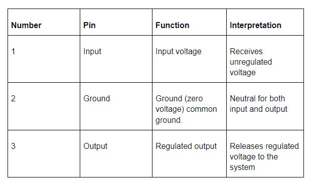
The pinout diagram below explains the 7812 pin configuration
7812 pin diagram
Where
1- Input pin
2- Ground pin
3- Output pin
Pin details of a 7812 IC

Please note a current difference in the voltage received and released by a 7812 pinout.
That voltage difference is outlined by the purpose of the input and output pins.
Features and Specifications
- 220 (TO) transistor outline package
- Affordable
- Instantly shuts down during when fiery
- Quickly shuts down in case of short circuit (built-in protection)
- Affordable
- Comfortably works in commercial devices
- 8MA standby current (relatively low)
- 35V Direct current (DC) highest input voltage
- 1.5-Ampere output current
- fixed output of 12V
- three pins
- Mounted through-hole
Special Offer: Get $100 off your order!
Email [email protected] to get started!
Replacement and Equivalent
Here are some standard voltage regulator ICs you can use If you cannot find a 7812 pin but still need a regulator that achieves 12v output.
- LM1084-12
- LM340-12
- LM317
- LM340A-12
Typical Application Circuits
As earlier stated, the 7812 pinout is a regulator that helps maintain a constant output voltage in circuits. Below we look at some courses that can utilize a 7812 regulator.
First, let us look at two low current circuits that use a 7812 pinout.
Low current circuit 1
Low current7812 application circuit
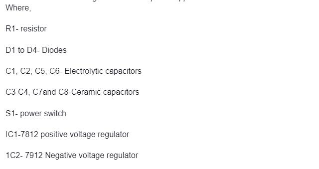
The above diagram showcases a +/-12 dual voltage or dual-powered circuit that uses a 7812 and 7912 pinout. Here the LM7812 IC regulator achieves +12V while the LM7912 regulator IC produces -12V.
This Low current circuit can deliver no more than 1 Ampere, making it suitable to be used in a preamplifier tone manager that has an AMP-OP course.
You can use the circuit only if your load does not exceed 300ma.
In the low current circuit, you can notice the unregulated supply of power shown by F1, D1, D2, C2, C1, C4, C4, S1, and T1.
Also, to reduce the ripple voltage that may arise from the two half-wave rectifier diodes in half-wave rectifier form.
Experts recommend the use of double filtering capacitors (C2and C4 in this case)
Note that the circuit above uses a CT15V and AC15V 300mA powered transformer.
As a result, when the 30V voltage is converted to direct current volts ( DCV), it rises to 42voltage direct current (VDC).
Then all the input 21VDC voltage gets referred to the 7912 and 7812 pinouts.
Finally, the two regulators then maintain a constant output voltage.
Low current circuit 2
Low current7812 application circuit
The above diagram utilizes only two capacitors, a power source, and the 7812 IC regulator.
Looking at the voltage probe, you will notice that a positive input voltage of 25V passes through the 7812 regulators.
However, the voltage released or output is 12V DC (direct current), showing a voltage difference.
Finally, the circuit diagram above uses ceramic capacitors as experts consider them faster than electrolytic capacitors.
Look at the diagram below to understand how the 7812 IC works to achieve a constant voltage preventing a voltage drop.
7812 pin voltage regulator
High Current Circuit
High current 7812 pinout application circuit

You can use the above circuit if you seek a 12V dual power supply that can comfortably handle 500mA.
The high current course above shares many similarities to the first low current circuit; nevertheless, there are slight component changes on it, such as;
- full-wave rectifier diodes that have 1N4007 (4 diodes).
- C6 and C5 capacitors filter ripple voltage directly to the output.
- C7 C4and C3 filter capacitors clean transient voltage coming from the input.
- A current limiting resistor enables the LED1 to show the power.
- The current size of the transformer changes with a secondary coil.
Parts you will need to make the above circuits.
- 0.5A Fuse
- 0.5W resistor
- LEDs (you can use any)
- 2 Ceramic capacitors 50V 0.1uF
- Electrolytic capacitors 35V 100uF
- 2 Electrolytic capacitors 35V 2200uF
- 1000V 1A, 1N4007 diodes
- 7812 IC regulator
- 7912 IC regulator
- ON/OFF switch
- 220V 1A transformer
How to Safely Long Run in a Circuit?
As with all-electric components, there are some measures you need to put in place to ensure effectiveness, longevity and reduce the risk of accident occurrence.
They include;
Firstly, ensure you check and confirm the pinout in advance of using it.
Secondly, store the 7812 pinouts in temperatures at a minimum of 65 degrees Celsius and a maximum of 150degrees Celsius.
Third, assemble the components of the integrated circuits on a perforated board.
Then, avoid operating the device in temperatures below 0 degrees Celsius and temperatures above 125degress Celsius.
When using the regulator, always use a heat sink that matches the heat produced. Moreover, you can use the formula; the heat produced = (input V less 5) × Output current for adequate heat sinking.
Lastly, operate your device within the minimum input voltage requirement and the maximum input voltage limit.
Applications
- Dual supply regulation
- Making toys
- Used in circuits requiring power distribution
- Phone chargers
- Limits current applications
- Used in micro-controlled devices
- Making of solar power equipment
Summary
Regulators have primarily reduced cases of electric device failure, thereby ensuring a longer lifespan for the devices.
Hence, after going through the article, we hope we have answered all your questions concerning the 7812 pinouts.
If you need more information on regulators, contact ourPCB, and we will gladly provide it.
Special Offer: Get $100 off your order!
Email [email protected] to get started!


