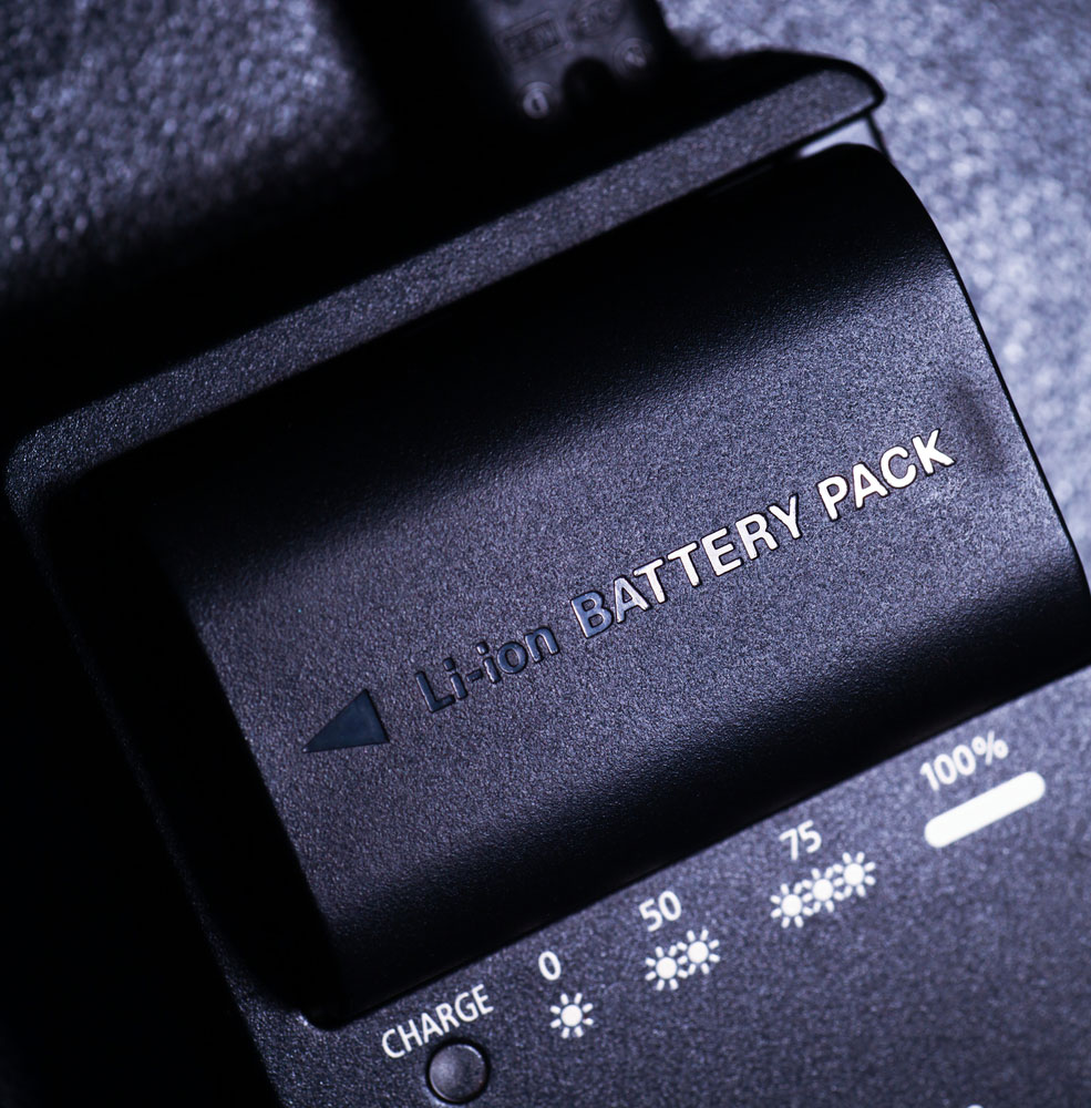
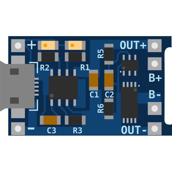
A li-ion or lithium-ion battery is a rechargeable battery that employs an intercalated lithium compound on the positive end and graphite at the negative terminal. In most consumer electronics, 3.7V Li-ion batteries are from computers torches to electric vehicle batteries. On the other hand, a battery charger is an application used for storing energy in a battery as it runs an electric current through it. They limit the rate at which current/voltage passes through batteries to prevent overcharging. Hence, this article will dive deep into highlighting the charging current or voltage and materials to use as we design the lithium-ion battery charger circuits.
Contents
- 3.7V Lithium-ion Battery charger Circuit- Schematic Diagram
- Lithium-ion Battery Charger Project- Using MOSFET, LM317
- Li-Ion Charger using a single MOSFET
- Lithium IOn Battery Charger Circuit using LM317
- Materials needed
- The Working of Li-Ion Battery Charger using IC 317
- Step by step Calibrations
- PCB Design
- Charging and Performance
- Advantages
- Disadvantages
- Conclusion
3.7V Lithium-ion Battery charger Circuit- Schematic Diagram
It is an example of a Li-ion battery charger that can charge a 3.7V lithium-ion battery using a 5VDC power supply. The Battery uses an MCP73831 microchip, a valuable advanced controller for limited space and cost-sensitive applications. The circuit applies a constant voltage/ current algorithm with pre-determined conditions and charge termination.
(A schematic diagram of a 3.7V Lithium-ion Battery charger)
Lithium-ion Battery Charger Project- Using MOSFET, LM317
Firstly, we must identify that lithium-ion batteries are more disposable to overcharging or high initial current, a feature known as charging at a 1C rate. At this point, C symbolizes the Ah value of the Battery receiving the charge. Typically, the standard value is 0.5C. However, it is not advisable to use these extreme charging as it causes stress on the Battery resulting in high temperatures. Nevertheless, here are a few battery charger ICs.

(image of a li-ion battery charger)
Special Offer: Get $100 off your order!
Email [email protected] to get started!
Li-Ion Charger using a single MOSFET
It is one of the cheapest and uncomplicated li-ion chargers you can make. To create this simple circuit, you will need one MOSFET, a timer, and a 470-ohm ¼ watt resistor. The course lacks battery temperature regulations, so remember to use a low input circuit current. The recommended constant amounts of current are approximately 0.5C.
(A drawing of a Li-Ion Charger circuit using a single MOSFET)
Lithium IOn Battery Charger Circuit using LM317
Materials needed
- Three resistors:R1(330Ω), RV1(1kΩ) and R2*(2.2Ω,1/2 -watt)
- Two capacitors: C1( 1000µF, 25V) and C2(100nF)
- Semiconductors: LM317 (Variable positive voltage regulator), BC547 (General purpose NPN transistor), and 1N4007 (Rectifier Diode)
- Miscellaneous
- Two Terminal block
The Working of Li-Ion Battery Charger using IC 317
The circuit employs the IC LM317 and NPN transistors for sensing and current limiter, hindering an overcharging situation. When current is allowed to flow in the course, the IC 217 limits the current and generates a 3.9V output voltage to the connected lithium-ion Battery. On the other hand, the temperature is controlled by the two NPN transistors connected to the ADJ pin. The ADJ pin is grounded such that if the transistors conduct, a short circuit is created, resulting in the output current to the Battery shutting off.
(A drawing of a Li-Ion Battery Charger circuit using IC 317)
Step by step Calibrations
- Disconnect the Battery for charging
- Connect the power supply input current
- Adjust the variable resistor until there is a full voltage output charge
- Connect the Battery
PCB Design
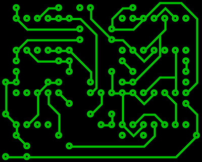
Below is a component side PCB of a lithium-ion battery circuit.

(an image of Li-ion charging module- component side)
Charging and Performance
During discharge, the charging process involves lithium ions navigating from the negative electrode to the positive electrode. The opposite happens when charging.
Li-ion batteries maintenance needs minimal requirements and simple instructions; however, they are essential applications. For instance, ensure you cut off current/ voltage at the whole charge level provide constant voltage and constant current input supply. Do not allow the Battery to discharge fully. Additionally, charging/discharging battery voltage affects the Battery's temperature, which you are within the room temperature range. It will have your Battery working successfully.
Advantages
- Accessible and cheap to manufacturer
- Very low self-discharge
- Old technology hence matured, and there is sufficient information about the batteries.
- Require little maintenance
Disadvantages
- Cannot store Battery while discharged
- Require protection from overcharging or discharging too far
- Aging with time, whether used or not
- Require protection from overcharging or discharging too far
- Battery aging with time, whether used or not
Conclusion
Generally, Li-ion batteries have a higher battery life span and significantly increase if the depth of every discharge is within the 80% of the rated capacity. Nevertheless, if manually monitoring your Battery is a task, you can adopt an automatic circuit to keep it safe and ensure longer battery life. For example, the TP4056 IC has an auto cut-off and automatic recharge feature. Finally, please get in touch with us for any questions about lithium-ion batteries or their circuits.
Special Offer: Get $100 off your order!
Email [email protected] to get started!


