In the realm of electronic component assembly, the choice between surface mount technology (SMT) and through-hole technology is pivotal. OurPCB specializes in SMT assembly, a modern technique that enhances the efficiency and capacity of printed circuit boards.
Choosing the new SMT Assembly can be arduous. Engineers must analyze the merits of hundreds of varieties and parts, whether in stock, how future supply looks, and the replacement cost of parts.
Whereas all these are vital aspects to choosing a type of PCB, there is a much more fundamental question that we should be asking – whether to select surface mount technology or through-hole.
This article delves into the differences between Through-Hole Technology (THT) and Surface Mount Technology (SMT). We’ll discuss the advantages, capabilities, and applications of both technologies. Let’s dive straight into what is surface mounting and through hole technology.
Contents
- What is Through-Hole Technology?
- Advantages
- Disadvantages
- Applications
- What is Surface Mount Technology?
- Advantages
- Disadvantages
- Applications
- Through-Hole Technology vs Surface Mounted Technology (THT vs SMT)
- Space Differences
- Pin Count
- Affordability
- Assembly Automation
- Performance
- How To Choose PCBA Technology
- OurPCB: Professional PCB Assembly
- What is Through-Hole PCB Assembly? SMT vs THT | FAQs
- What components are used in through-hole technology?
- What is the difference between VIAs and through holes?
- What is reflow in SMT?
What is Through-Hole Technology?
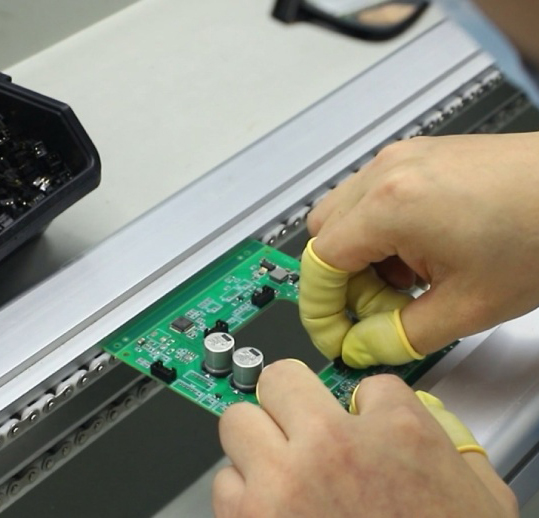
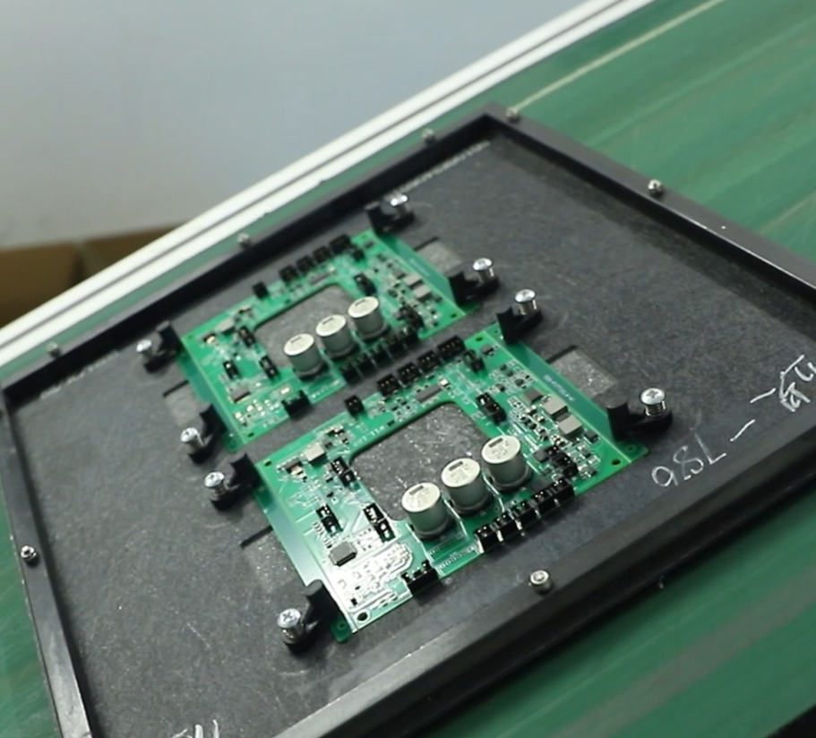
So, what is a through hole? Through hole technology, also called thru hole technology, is when the leads one components are fitted through drilled holes in PCBs (Printed Circuit Boards). It is then soldered onto pads that are on the other side.The through-hole components can be soldered to the pads by manual assembly or automated insertion through hole mounting machines.
Through holes are considered one of the older designs by many, whereas surface mount is pretty new. And to some extent, in terms of practical applications, the through hole assembly is still significantly better in specific scenarios.
In the 1950s, printed circuit boards came with tracks written on only one side. When you insert the leads of a component into the board, you increase the drilled holes.
Therefore, the negative electrode side has an element soldered to the copper on the board. The later stages saw the introduction of tracks on both sides of the boards and inner layer tracks of the printed circuit board.
It give way to plated through-hole technology, making it possible to attach through hole components to the inner layer of the circuit board, improving the concept of through-hole technology PCBA assembly.
(Caption: Radio Components on PCB using Through-Hole Technology )
Advantages
- The leads must be inserted through the drilling holes. It makes the component sturdier. They can handle much environmental stress, mechanics, heat, and pressure.
- PCBs of THM are also suited for collisions or extreme accelerations, so it is ideal for advanced applications like military or aerial equipment or transformers.
- THM can be easily replaced, so the prototype is mainly for testing applications.
Disadvantages
- The bigger component size and one-sided availability make the manufacturing cost higher.
- The components of THM are also placed and soldered manually, leaving little room for automation like SMT, so it is expensive. Boards with THM components must also be drilled, so no tiny PCBs come at a low cost if you use THM technology.
(Through-hole)
Applications
- High-Power Electronics: Thru hole or through hole is suitable for handling high currents and voltages.
- Industrial Equipment: Provides durable connections for machinery and control systems.
- Prototyping: THT makes it easy to do manual assembly and modification in prototypes.
- Automotive Electronics: Used in critical automotive systems that need strong connections in thru-hole components.
- Military and Aerospace: THT offers reliability and can handle extreme conditions.
What is Surface Mount Technology?
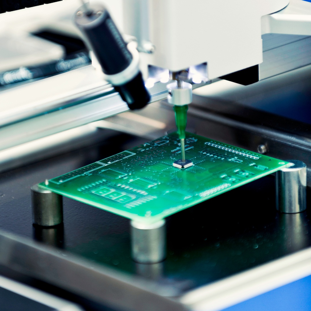
Next, let’s get into what does surface mount mean in PCBS. Unlike thru hole components, a PCB surface mount is secured just by solder on the board. There are also various surface mount types.
Surface mounted technology became known in the 1960s, and its applicability slowly rose in the 1980s. This surface-mount technology was known as planar mounting in the beginning.
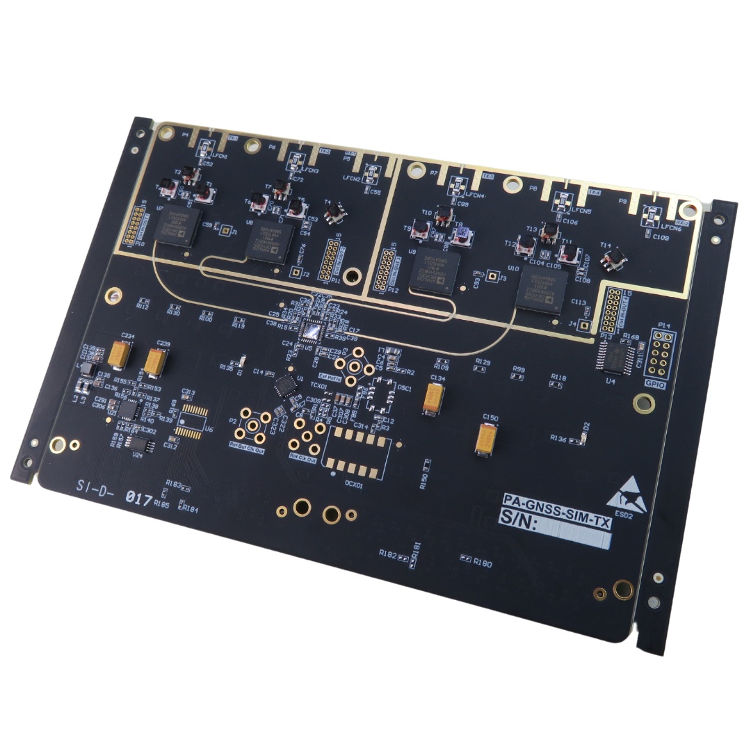
The technique of surface mounting involved SMDs (Surface Mounted Devices) or surface mound packages. Components in this board have lead surrounding or underneath.
What separates surface mounted components from through-hole mounting technology is that there is no need to drill holes in the circuit board to connect the tracks and the components.
Establishing relationships through leads, the ingredients are in direct touch with the PADs of the circuit board. You can add solder paste to the PAD with the help of stencil solder.
A pick-and-place machine is also responsible for initially placing the components on the solder paste set above the PAD. After setting, these surface mount components must be placed in a reflow oven or introduced in a vapor phase to be soldered permanently in the surface mount PCB assembly.
Advantages
- SMT has the fewest components, and we can place them quickly. Components can be mounted on both sides for automated welding. All these make it much cheaper.
- Small, lightweight PCBs predominantly use the SMT because they weigh less than the THM boards.
- The components are packed tight on the board, so this is a distinct advantage, with many electronics focusing on reducing the size.
- The SMT components are smaller and can be placed much faster during assembly, so the production cost is low.
Disadvantages
- SMT is not without challenges despite the many advantages it offers. We can quickly place components, and the entire thing can be automated – but the caveat is the machines that can do that cost very high.
- It can effectively lead companies to push low-volume boards to higher prices, Just because of the significant capital investment.
- The surface mount technology requires a lot of precision due to the components' buried vias and size.
- The design also involves a lot of skill because any violation of the pad layout guidelines could result in tombstoning. That means the product can be reduced largely.
Applications
- Consumer Electronics: Usually used in small devices like smartphones and laptops.
- Medical Devices: Can be used in small and precise medical equipment.
- High-Density Circuit Boards: Allows for higher component density for mini electronics.
- Telecommunications: SMT is important for advanced communication devices and networking hardware.
- Automated Manufacturing: Enables high-speed, automated assembly processes.
Special Offer: Get $100 off your order!
Email [email protected] to get started!
Through-Hole Technology vs Surface Mounted Technology (THT vs SMT)
Through-Hole Technology inserts components through PCB holes, providing strength but taking more space. Surface Mounted Technology places components directly on the PCB surface, enabling higher density and faster production.
Now that we’ve gone through the through-hole and surface mount meaning, let’s talk about how they compare. These are the main differences between thru-hole or through hole technology and surface mounted technology.
Space Differences
In the case of surface-mounted technology, the PCB can mount more components than thru holes due to two factors.
First, the elements of the SMT are smaller themselves, and then they can also be placed on either side of the board.
The space problem prominent in the through-hole is overcome in the surface mount technology. With SMT, space can get smaller, lighter, faster, and more powerful.
Pin Count
SMT beats THM because it can hold a much higher pin count. Pin count on a component board is simply the lead count of the component, which is the total number of the part leads that a printed circuit board can fit.
The leads of through-hole components have become replaceable with the invention of smaller parts called VIAs. They allow conduction between the various levels of the PCB. By doing so, they eliminate the need for leads going through a hole in electronics.
On the other hand, surface mount components are much higher in performance, have shorter points, and the pins are much more interconnected, which leads to better speed.
Affordability
SMT assembly components are usually cheaper than through-hole components. The through-hole method requires drilling holes in the empty side of the board. It is a task that takes a lot of time and costs a hefty amount.
THM also limits the routing area in any board with multiple layers. It is only because the holes should pass through all these layers.
When we look at the through-hole PCBA, the assembly side comes at a fraction of the cost for placing components than a surface mount. Undeniably, the THM issue is the drilling cost, which makes it more expensive and time-consuming than the SMT. The components also have to be hand soldered on the board.
On the other hand, the surface mount assembly has a plurality of terminals soldered to the tubular body. Compared with flat chip VIAs used, the cost of these components is much cheaper.
Since the SMT PCBA offers a much higher volume and soldering can be automated, they are cheaper.
Assembly Automation
Surface Mount Technology is more helpful for assembly automation. SMT can be produced in high volume at much lower costs because SMT has the possibility of assembly automation. This also results in lower costs during production.
Automated assembly can save PCB assembly time even more. Many PCB suppliers currently have production machines with surface mount technology. It can be assembled accurately and quickly.
From this point of view, it is faster and more advanced than through-hole technology. If you are looking for assembly speed and need to produce PCBs in large quantities, you can choose surface mount technology.
Ask your PCB supplier if they can provide it.
Performance
Through-hole technology pays more attention to performance.
The way in which through-hole components are soldered makes it durable in high heat and shock scenarios.
The through-hole elements have long led, and these can be inserted through the drill holes, ultimately being fastened to the copper pads underneath. It is a secure process that is much more reliable than the mounting style in SMT. It also makes it possible for through holes to endure higher stress conditions.
The through-hole components are also more significant, and while that makes space an issue, it helps with high-power applications. Parts can also be easily removed and replaced in urgent situations, which is not possible in SMT PCBA.
How To Choose PCBA Technology
SMT assembly | Through-hole | |
Unsuitable for high stress | Surroundings | Good for high-stress and high heat |
Less expensive production | cost of production | More expensive due to manual soldering and drilling |
Prototyping or production | The level of development | Proof of concept or prototyping |
Placed on both sides | Circuit board layout | Placed on one side |
Low Power | Main application | High power |
OurPCB: Professional PCB Assembly
There are certain advantages and disadvantages to both SMT and THM.
SMT's primary applicability and demand come from many electronic devices pushing for a smaller size, which SMT can provide. It is why 90% of all the printed circuit boards made today are SMT.
However, there is no denying the resilience of the THM in specific applications. The high stress, thermal, and environmental durability make it ideal for aerodynamics and military applications.
If you need PCB assembly, whether through-hole technology or surface mount, OurPCB can provide you with professional technology.
What are you waiting for? You can contact us now for professional services.
What is Through-Hole PCB Assembly? SMT vs THT | FAQs
What components are used in through-hole technology?
Through-hole technology components includes resistors, diodes, capacitors, integrated circuits, and transistors. Usually, THT components are much bigger than SMT components, so they’re easier to solder.
What is the difference between VIAs and through holes?
The main difference between VIAs and through holes is that VIAs have a barrel, pad, and anti-pad, while through-holes have a hole plated with copper across the entire PCB.
What is reflow in SMT?
Reflow soldering in SMT is a way to attach SMT components to PCBs. This is done by pre-heating the components or solder paste and then melting the solder. The process should not cause overheating damage.
Special Offer: Get $100 off your order!
Email [email protected] to get started!