Contents
- Key Takeaways
- What are the Common Electrical Circuit Board Components?
- What Is an Electronic Component?
- What Are the Different Types of Components?
- Active Components
- Passive Components
- Identifying Circuit Board Components
- Visual Identification
- Using a Multimeter
- Reference Materials
- Common Issues with Circuit Board Components
- Identifying Faulty Components
- Troubleshooting Techniques
- Replacement and Repair Tips
- OurPCB: Experienced PCB Assembly Services
- Essential PCB Components: A Comprehensive Guide FAQs
- How do you place PCB Components?
- How are components connected in a PCB?
- What are PCB boards used for?
- What are printed circuit board made of?
- How are PCB Components Identified?
Key Takeaways
- PCBs organize and connect essential components for electronic functionality.
- Resistors, capacitors, diodes, and ICs play specific roles in circuit operation.
- Component markings and labels aid in troubleshooting and repair.
- Multimeters and visual inspections help identify faulty PCB components.
- OurPCB offers expert assembly to ensure precise, reliable component placement.
What are the Common Electrical Circuit Board Components?
Below is a table that provides a breakdown of common circuit board components and their descriptions, helping you learn how these parts contribute to the overall functionality of a PCB.
| Component | Image | Description |
|---|---|---|
| Resistors | 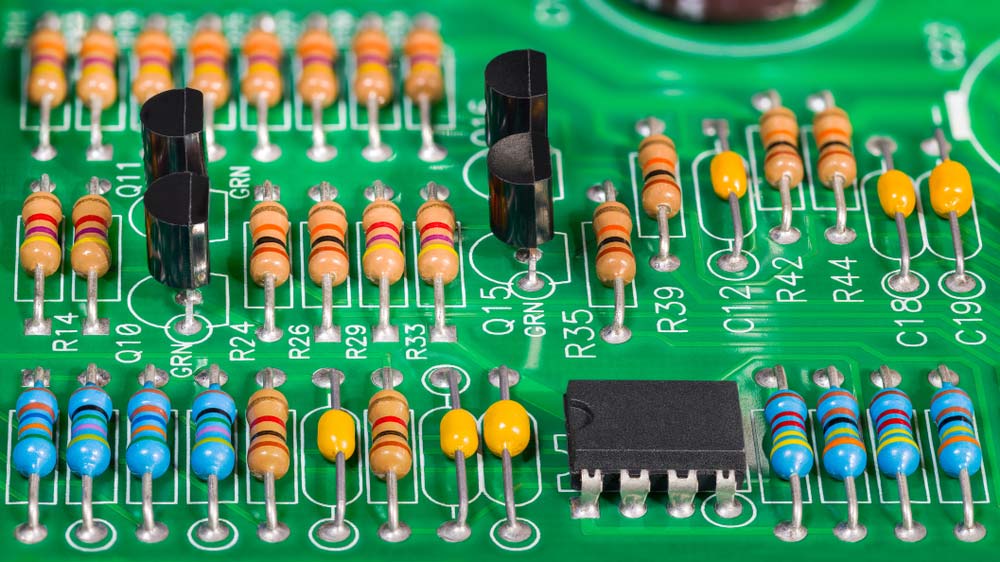 |
A resistor opposes electrical current in a circuit, useful for adjusting signal levels, splitting voltage, or controlling LED brightness. Types include fixed and variable resistors, with the latter ideal for real-time adjustments or sensing conditions like light and humidity. |
| Capacitors | 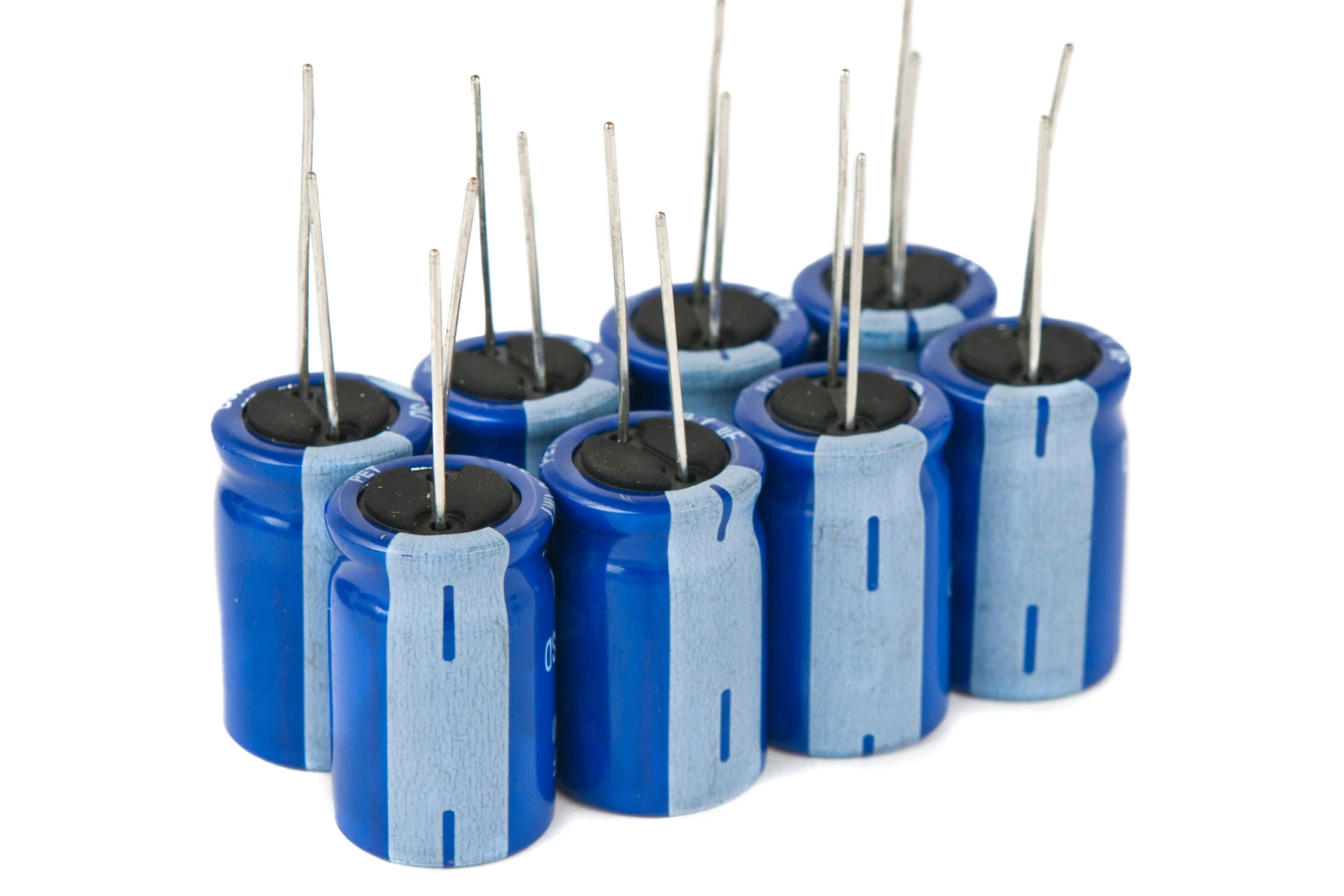 |
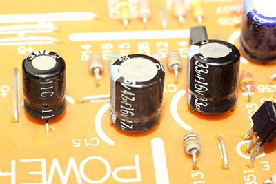
Capacitors store electrical charge on two plates separated by a dielectric, air, or vacuum. They filter noise, stabilize voltage, and create circuit resonance. |
| Diodes | 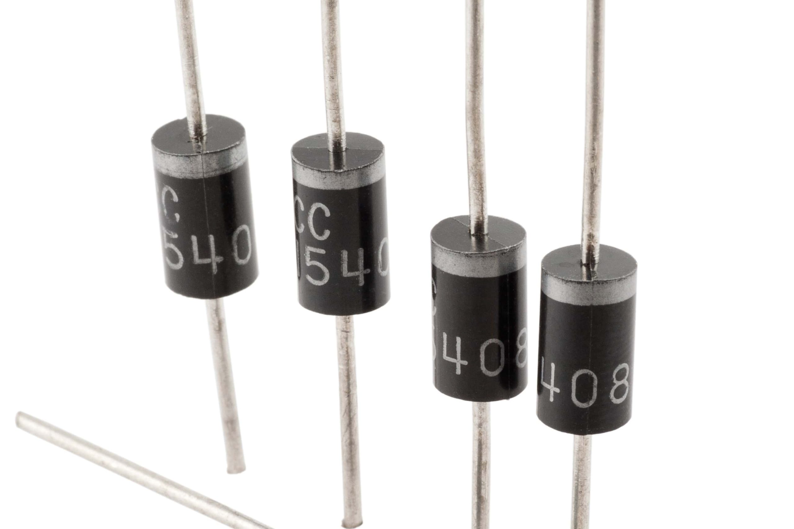 |
Allow current to flow in one direction while blocking it in the opposite. |
| Inductors |  |
An inductor stores energy as a magnetic field when current flows through it. Made of insulated wire around a core, it resists changes in current due to Lenz's law. |
| Transformers | 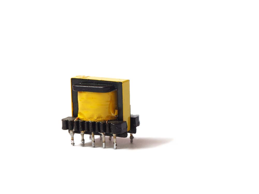 |
A transformer transfers AC energy between circuits through magnetic coupling, stepping up or down voltage, making it ideal for audio amplifiers and power supplies. |
| Crystal Oscillators |  |
Generate precise clock signals for timing in circuits. |
| Sensors |  |
Detect physical conditions (e.g., temperature, pressure) and convert them to signals. If you're working on security or automation systems, Passive Infrared (PIR) sensors are essential for detecting motion in a room or space. |
| Silicon Controlled Rectifier | 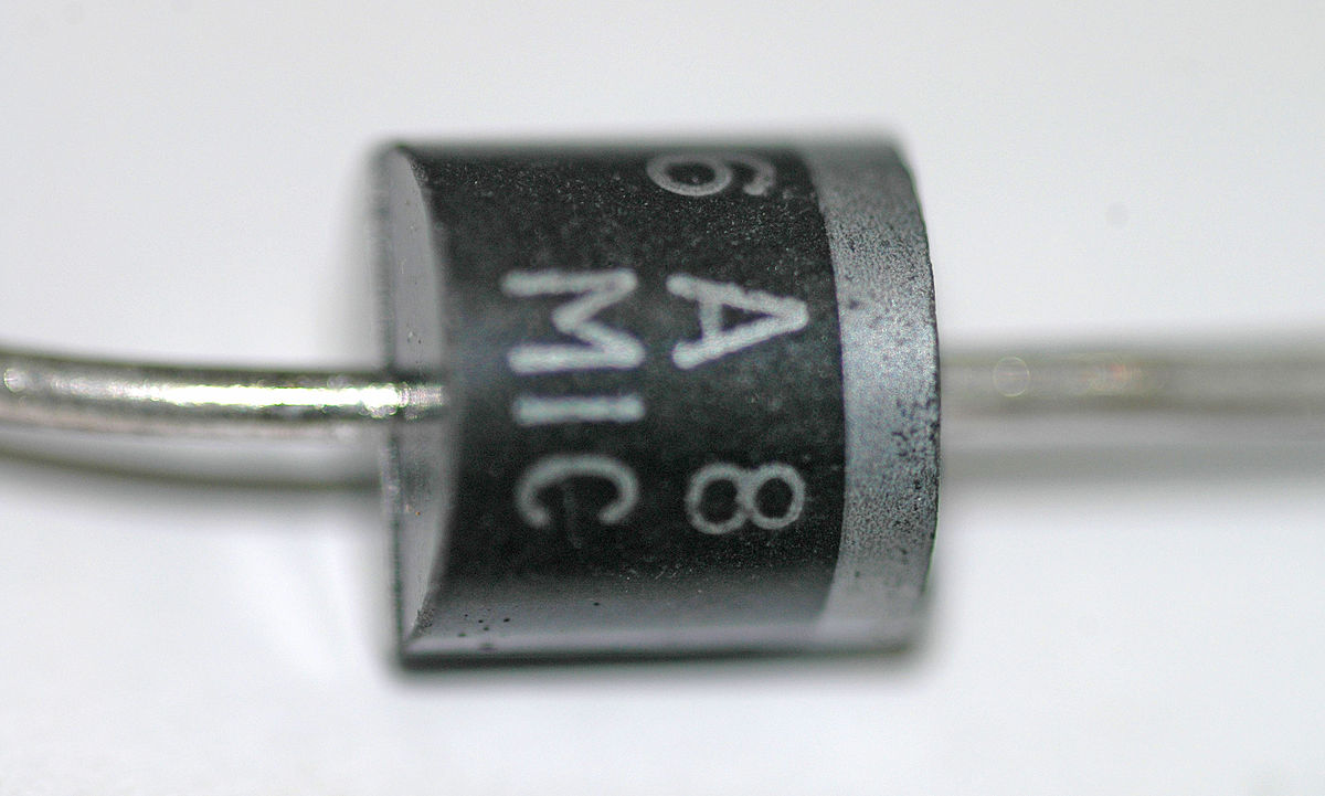 |
A semiconductor switch that controls large amounts of power with small signal inputs. |
| Battery |  |
Store energy to power the circuit. |
| Relays |  |
Electrically controlled switches used to control circuits. |
| Blank PCB |  |
The foundation of a circuit, where components are placed and connected. |
| LED | 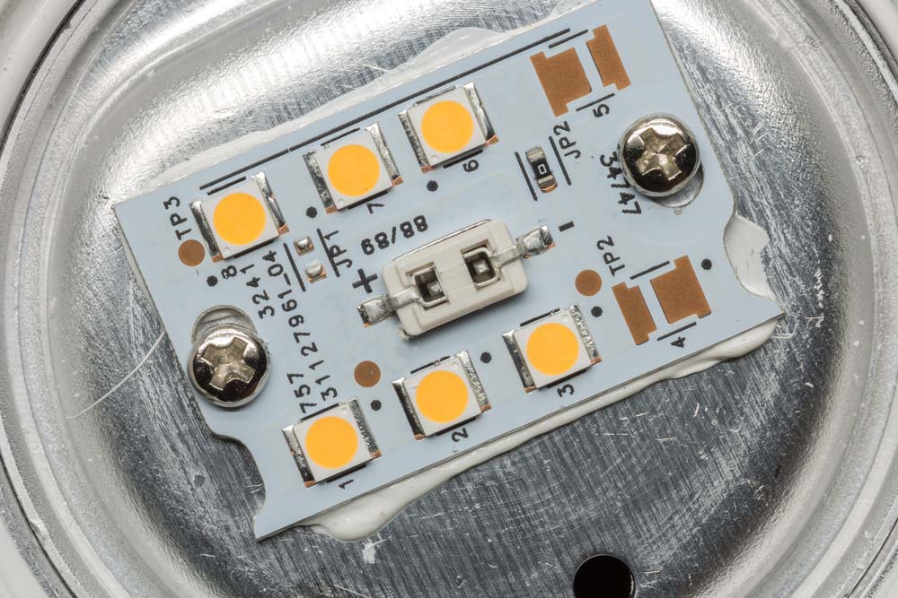 |
Light-emitting diode used for indication or lighting. |
| Screen Printing | 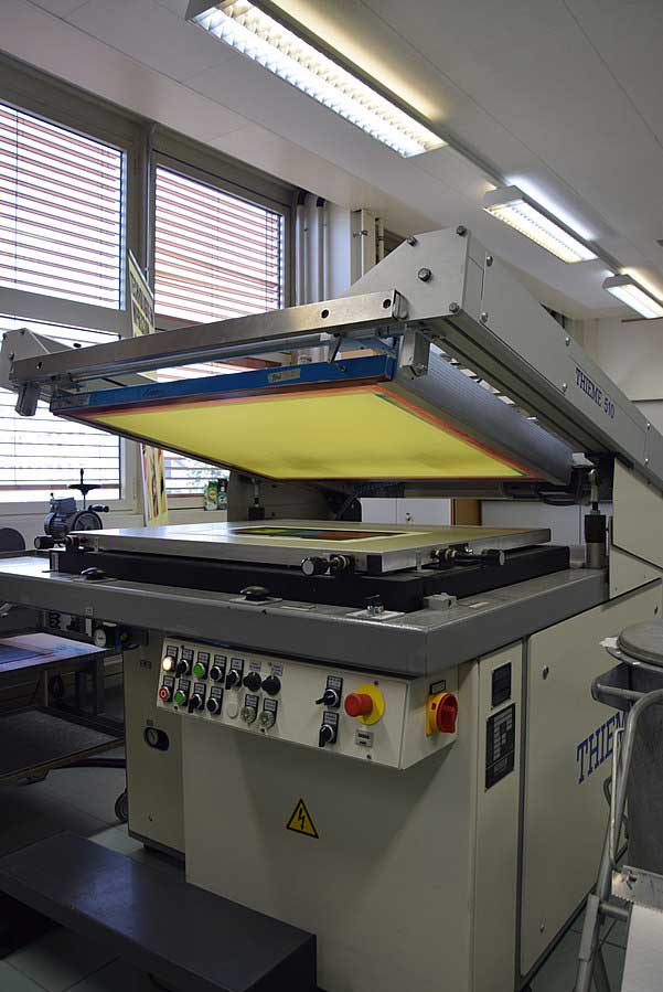 |
Method for applying ink to the PCB surface to label components. |
| Fuse | 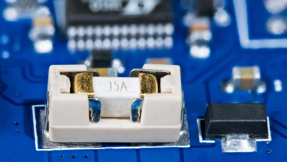 |
Fuses contain a wire rated for specific voltage and current. If exceeded, the wire melts, protecting the circuit from overcurrent damage. For more on protecting your circuits, consider understanding fast-blow fuses, which offer rapid protection in high-current scenarios. |
| Digital Electronics | Electronics that use digital signals for processing. | |
| Field-Effect Transistor | 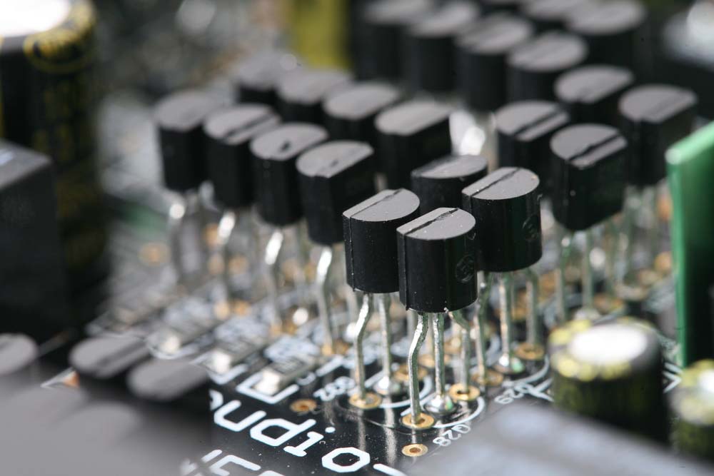 |
Controls electrical behavior using an electric field. |
| Integrated Circuit | 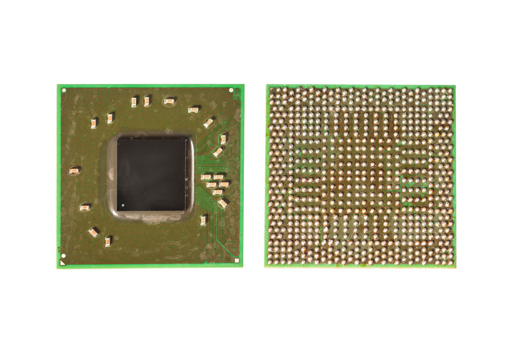 |
A compact circuit with multiple electronic components integrated on a chip. |
| Potentiometers | 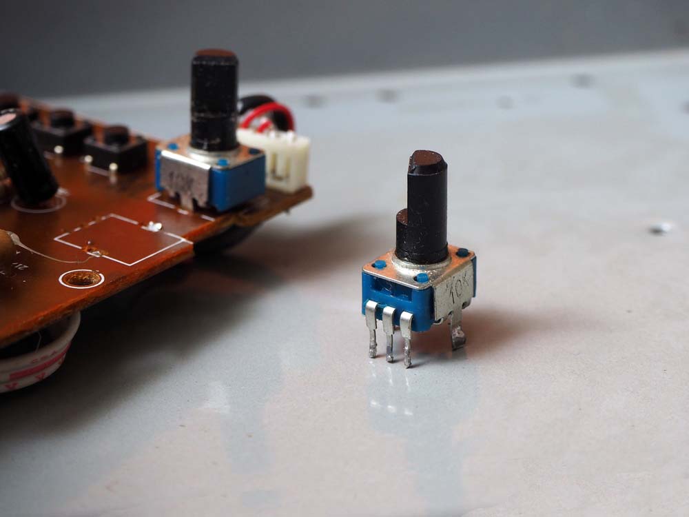 |
Potentiometers are three-terminal variable resistors with a sliding contact that adjusts voltage, ideal for controlling audio volume. |
| Circuit Boards | 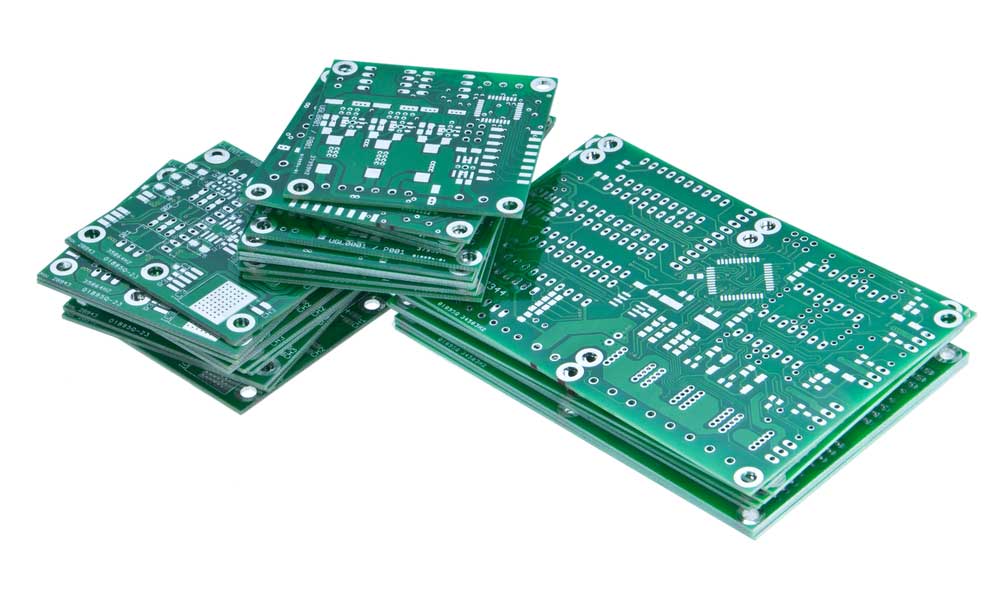 |
The platform where electronic components are mounted and connected. |
| Switch | 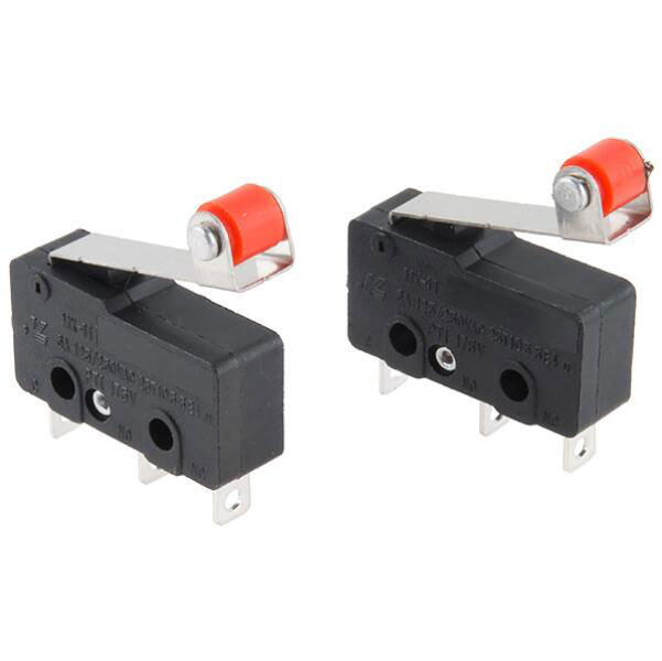 |
Switches regulate the flow of electric current through circuits and require manual or physical input to cut or reconnect the power supply. |
| Connectors |  |
Provide electrical connections between different components or devices. |
| Solder Mask | 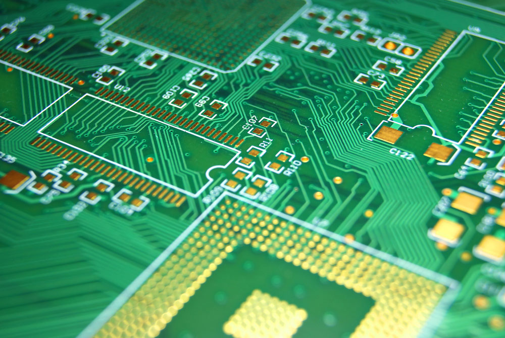 |
Protective layer applied to the PCB to prevent oxidation and shorts. |
| Copper Layer | 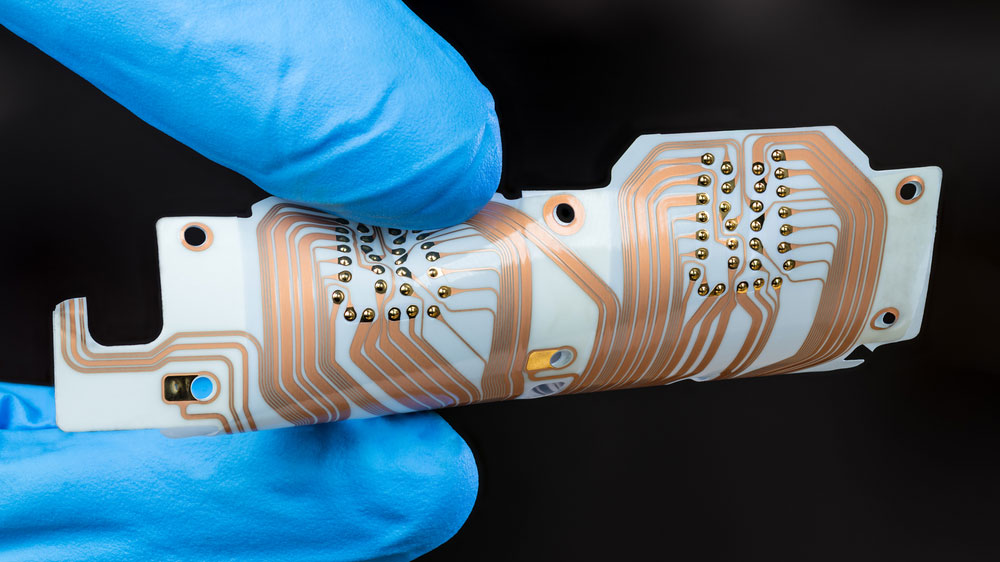 |
Conductive layer on the PCB that forms the circuits and connections. |
| Varistors | 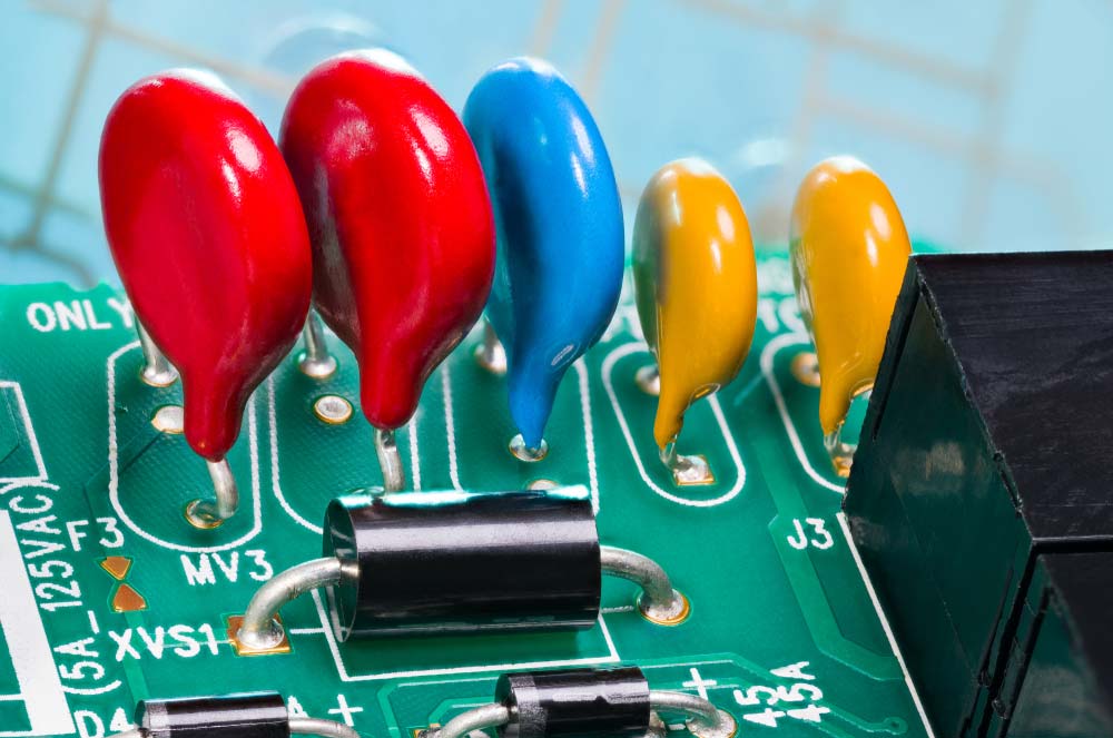 |
Varistors are voltage-dependent resistors that protect circuits from spikes and surges. Their resistance decreases as voltage increases. |
| Thermistors | 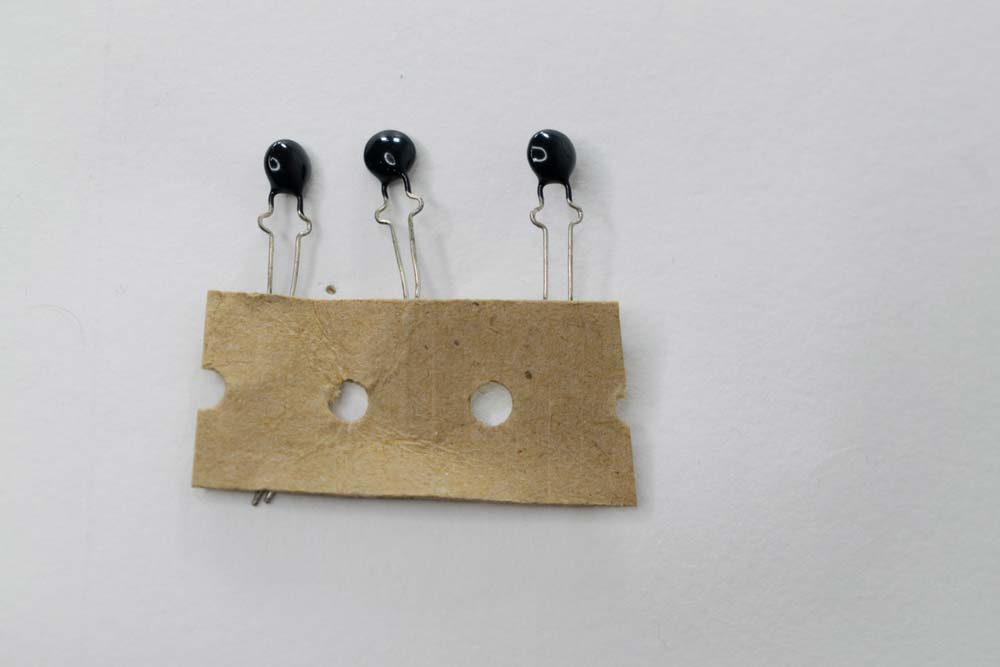 |
Thermistors are variable resistors used as temperature sensors. Their resistance changes with temperature and can be NTC (decreasing resistance) or PTC (increasing resistance). |
| Resistor Networks | 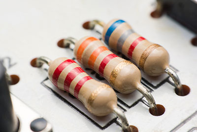 |
Resistor networks group multiple resistors in one package, commonly used in digital circuits to manage current and voltage flow. |
| PCB Traces |  |
PCB traces are conductive paths, usually made of etched copper, that transmit power and signals to components on the board. |
| Active Components |  |
Active components add energy to circuits, requiring external power for amplification and switching. Key types include operational amplifiers, microprocessors, transistors, and diodes, which are used for voltage amplification, processing, switching, and AC to DC conversion. |
| Voltage Regulators | 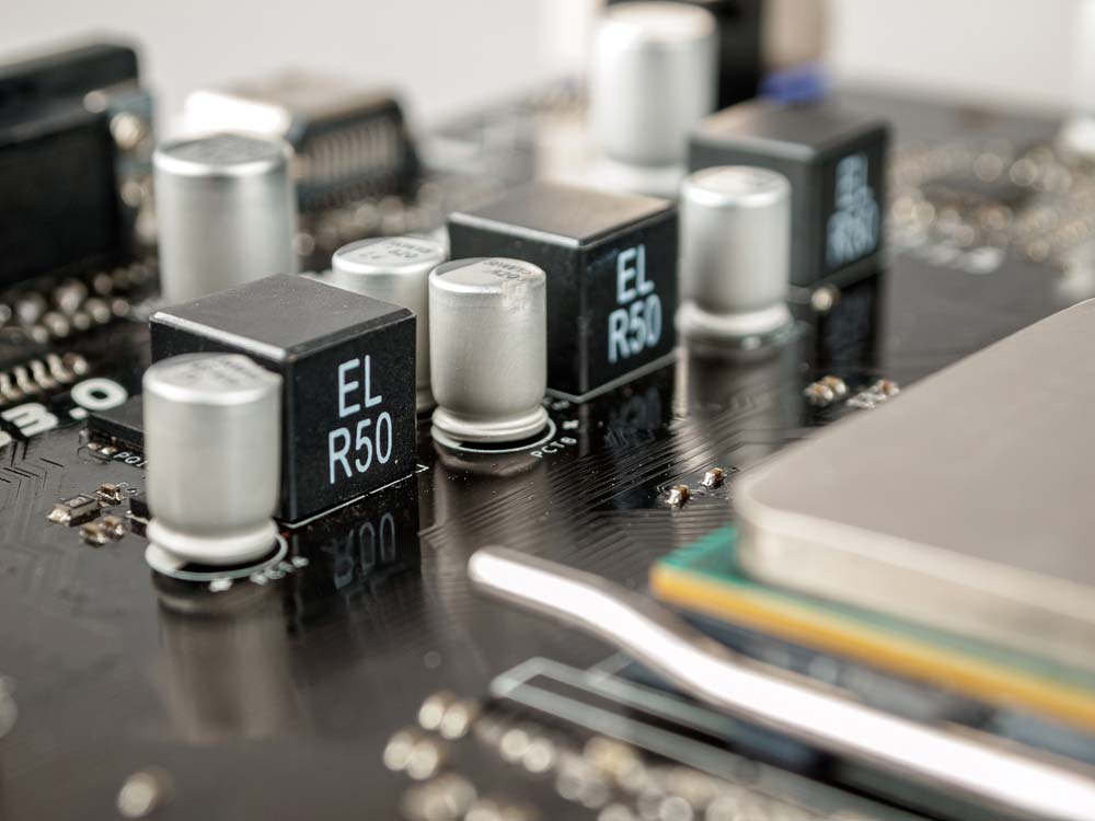 |
Voltage regulators ensure stable output voltage. Key types include linear, switching, LDO, buck, boost, and charge pump regulators, each suited for different power and efficiency needs. |
| Optoelectronics |  |
Devices that convert light to electrical signals or vice versa, such as LEDs, photoresistors, and photodiodes. LEDs emit light when current flows in forward bias. |
What Is an Electronic Component?
An electronic component is a basic part used to control the flow of electricity. These parts come in many shapes and sizes, each with a specific function. They can be found in almost all electronic devices, from flashlights to complex systems like computers. 7-segment displays, for example, are commonly used for visualizing numerical data in various devices, including calculators and clocks, by lighting up specific segments of a display. Click here for understanding how 7 segment displays work.
Electronic components work together to perform tasks like amplifying signals, storing data, or converting energy. Understanding these components is the first step to learning how electronic devices operate and are built.
Special Offer: Get $100 off your order!
Email [email protected] to get started!
What Are the Different Types of Components?
Electrical electronic components can be divided into two main categories: active and passive components.
Active Components
Active components are parts that need an external power source to work. They can control the flow of electricity, amplify signals, or switch it on and off.
Transistors
Transistors are semiconductor devices that can amplify or switch electronic signals and electrical power. They work by using a small input current to control a larger output current and are used in amplifiers, switches, and signal modulators. Transistors are used in devices like hearing aids, computer memory chips, and smartphones.
Types of Transistors
- Bipolar junction transistors (BJT) have three layers of semiconductor material and can amplify current. They come in NPN and PNP varieties, with NPN being more common due to easier manufacturing.
- Field-effect transistors (FET) control the flow of current by applying a voltage to an electric field. They include Junction FETs (JFETs) and Metal-Oxide-Semiconductor FETs (MOSFETs). MOSFETs are widely used for their efficiency and low power consumption.
Integrated Circuits (ICs)
Integrated Circuits (ICs) are like miniature circuit boards, packing many components into a single tiny chip. They can perform complex functions like processing signals, storing data, or controlling other devices.
Types
- Analog ICs handle continuous signals and are used in audio and radio frequency applications.
- Digital ICs handle binary signals and are used in computers and digital systems.
- Mixed-Signal ICs combine both analog and digital functions on a single chip.
Active Diodes
Active diodes, also known as active rectifiers or synchronous rectifiers, use additional components like transistors or MOSFETs to improve performance. These components need an external power source to operate.
Types of Diodes
- Light-emitting diodes (LED) emit light when current passes through them.
- Zener diodes allow current to flow in reverse direction when a specific voltage is reached.
- Schottky diodes are known for their low forward voltage drop and fast switching.
Vacuum Tubes
Vacuum tubes control electric current flow in a high vacuum between electrodes and were an early form of electronic amplifier and switch.
Vacuum tubes were once widely used in radios, televisions, and other electronics, but have mostly been replaced by transistors and ICs. However, they’re still used in some high-end RF transmitters, audio amplifiers, and specialized scientific equipment.
Types of Vacuum Tubes
- Triodes have three electrodes and can amplify signals.
- Tetrodes have four electrodes, reducing interference in amplification.
- Pentodes have five electrodes, offering improved amplification.
Passive Components
Passive components don’t need an external power source to function. They can’t amplify signals, but they can store energy or resist the flow of electricity. These parts help shape and manage the signals within electronic devices.
Resistors
Resistors limit or control the flow of electrical current in a circuit, like a kink in a hose reducing water flow. They’re used to set voltage levels, divide voltages, and limit current to protect other components.
Types of Resistors
- Fixed resistors have a set resistance value.
- Variable resistors allow for adjustment of resistance.
Capacitors
Capacitors store electrical energy in an electric field and can release it quickly when needed. They’re used for filtering, smoothing, and timing circuits. Capacitors are used in power supplies, audio circuits, radio tuners, and many other applications.
Types of Capacitors
- Ceramic capacitors use a ceramic material as the dielectric and are mostly used in high-frequency applications.
- Electrolytic capacitors have a larger capacitance and are used in low-frequency applications.
- Tantalum capacitors are known for their reliability and stability in small sizes.
Inductors
Inductors store energy in a magnetic field when electrical current flows through them. They’re found in power supplies, radio circuits, motors, and other applications where filtering or energy storage is needed.
Types of Inductors
- Fixed inductors have a set inductance value, used in applications like filters and chokes.
- Variable inductors allow for adjustment of inductance, used in tuning circuits.
Passive Diodes
Passive diodes are semiconductor devices that allow current to flow in only one direction. They don’t generate or amplify power; they only control the direction of existing current flow. What makes them different from active diodes is that passive diodes don’t need an external power source to operate.
Types of Passive Diodes
- Standard rectifier diodes are the most basic type of diode, primarily used to convert alternating current (AC) to direct current (DC). They allow current to flow in one direction while blocking it in the opposite direction.
- Zener diodes allow current to flow in the reverse direction when a specific breakdown voltage is reached. This is used for voltage regulation to maintain a stable output voltage in power supplies.
- Schottky diodes have a low forward voltage drop and fast switching speeds. They’re commonly used in high-speed switching applications and for reducing power loss in power supplies.
- Light-emitting diodes (LEDs) emit light when current flows through them and are used as indicator lights and in display technologies.
- Photodiodes convert light into electrical current. Often used in light detection applications, like solar cells and optical communication systems.
Relays
Relays are electrically operated switches that can control a high-current or high-voltage circuit with small control signals. They are used in industrial control systems, automotive applications, and many other areas where electrical isolation or high-power switching is needed.
Types of Relays
- Electromechanical relays use moving parts to open or close the circuit.
- Solid-state relays use electronic components without moving parts, offering faster switching and longer life.
Circuit Breakers
Circuit breakers protect circuits from damage caused by overcurrent or short circuits. They automatically interrupt the flow of current when it exceeds a safe level.
Types of Circuit Breakers
- Miniature circuit breakers (MCB) protect against overload and short circuits in small-scale applications.
- Molded case circuit breakers (MCCB) protect larger-scale industrial applications.
Fuses
Fuses are sacrificial devices that protect circuits by melting when the current exceeds a safe level. They’re designed to be replaced once they’ve blown. Fuses are used in electronics, automotive circuits, and household appliances for overcurrent protection.
Types of Fuses
- Cartridge fuses are cylindrical in shape and used in various applications.
- Blade fuses are commonly used in automobiles.
- Resettable fuses automatically reset after the fault is cleared.
Switches
Switches are used to open or close electrical circuits, controlling the flow of current.
Types of Switches
- Toggle switches are operated by a lever.
- Push button switches are activated by pressing a button.
- Rotary switches are operated by rotating a knob.
Identifying Circuit Board Components

| Technique | Description |
|---|---|
| Visual ID | Identify by size, shape, color, and labels (e.g., "R" for resistors, "C" for capacitors). |
| Multimeter | Test resistance, capacitance, and continuity to verify component values. |
| Reference Materials | Use datasheets, diagrams, and online resources for specs and troubleshooting. |
Visual Identification
Visual identification is the first step in recognizing circuit board components. By examining the size, shape, color, and markings on the components, you can often determine what they are and what they do. Key points to consider include:
- Component Labels: Most circuit boards have printed labels or symbols next to components, such as "R" for resistors, "C" for capacitors, "L" for inductors, "Q" for transistors, and "U" for integrated circuits.
- Color Codes: Resistors often use color bands to indicate their resistance values. Capacitors may have printed numbers indicating their capacitance.
- Shapes and Sizes: Components like resistors, capacitors, and inductors have distinctive shapes. For example, resistors are cylindrical with color bands, while electrolytic capacitors are typically cylindrical with one flat end.
Using a Multimeter
A multimeter is an essential tool for testing and verifying the functionality of circuit board components. It can measure resistance, capacitance, and voltage, helping you to identify and confirm the status of components. Here’s how you can use a multimeter:
- Testing Resistors: Set the multimeter to measure resistance and touch the probes to both ends of the resistor. The reading should match the resistor’s color-coded value.
- Testing Capacitors: To check a capacitor, set the multimeter to the capacitance setting, and connect the probes to the capacitor terminals. The reading should be close to the value printed on the capacitor.
- Testing Diodes and Transistors: Use the diode setting on the multimeter to test diodes and transistors. For diodes, check for continuity in one direction only. For transistors, test the junctions between the base, collector, and emitter.
Reference Materials
When visual identification and multimeter testing are not enough, reference materials such as datasheets, circuit diagrams, and online databases can be invaluable. These resources provide detailed information on component specifications, pin configurations, and how they are used in circuits:
- Datasheets: Available from manufacturers, datasheets provide detailed technical information about specific components, including electrical characteristics, pin layouts, and recommended usage.
- Circuit Diagrams: Schematics and diagrams help you understand how components are connected within a circuit, aiding in identification and troubleshooting.
- Online Resources: Websites and databases dedicated to electronics offer searchable catalogs of components, cross-reference tools, and forums for discussing identification challenges.
Common Issues with Circuit Board Components
Circuit board components can encounter a variety of issues, often leading to device malfunction. Understanding these common problems can help you troubleshoot and resolve issues more effectively.
Identifying Faulty Components
Faulty components are a primary cause of circuit board failures. Common signs of component failure include:
- Burn Marks: Indicate overheating or a short circuit. Components like resistors and ICs may show visible signs of damage.
- Bulging or Leaking Capacitors: Electrolytic capacitors may bulge or leak electrolyte when they fail, often due to excessive heat or age.
- Cracked or Broken Components: Physical damage, such as cracks in resistors or transistors, can render components non-functional.
Heat-related failures are particularly common in high-power circuits, making effective PCB thermal management essential for preventing component damage and ensuring long-term reliability.
Troubleshooting Techniques
Effective troubleshooting requires a systematic approach to diagnosing issues:
- Visual Inspection: Start by visually inspecting the circuit board for obvious signs of damage, such as burn marks, corrosion, or loose connections.
- Component Testing: Use a multimeter to test individual components, comparing readings to expected values.
- Circuit Tracing: Follow the circuit paths to identify potential issues with connections or component interactions. Use the circuit diagram for reference.
Replacement and Repair Tips
When a component is identified as faulty, replacement or repair may be necessary:
- Component Sourcing: Ensure you source the correct replacement components, matching specifications like resistance, capacitance, and voltage ratings.
- Safe Removal: Use appropriate tools, such as a soldering iron and desoldering pump, to safely remove faulty components without damaging the board.
- Proper Installation: When installing new components, ensure correct orientation and secure soldering to maintain reliable connections.
OurPCB: Experienced PCB Assembly Services
Understanding printed circuit board components is essential for anyone working in circuit design, from beginners to experienced engineers. Each part, from small components that regulate current to elements that store energy in a magnetic field, plays am important role in creating reliable, efficient PCBs.
At OurPCB, we bring years of experience to PCB assembly, ensuring that every component in your design is perfectly placed to achieve the bestperformance. Whether you're following our beginner's guide or developing a complicated project, OurPCB’s team is here to bring your ideas to life with precision and quality. Ready to take your PCB from design to reality? Contact OurPCB today to get started with expert circuit board assembly services you can trust.
Essential PCB Components: A Comprehensive Guide FAQs
How do you place PCB Components?
In PCB design, components are placed according to the pcb layout, optimizing space and signal paths. Proper placement of passive components and active elements is important for the assembly process to ensure efficient electronic circuit performance.
How are components connected in a PCB?
Components in PCBs are connected by copper traces that route electronic signals through the board. These connections can use through-hole PCB components or surface mount technology, depending on the design and pcb manufacturing requirements.
What are PCB boards used for?
PCB boards are used to support and connect components in modern electronic devices, allowing circuits to function as intended. They organize and manage complex electronic signals across various systems for different printed circuit board applications, from computers to appliances.
What are printed circuit board made of?
Printed circuit boards are typically made of layers of fiberglass, copper, and epoxy, providing insulation and conduction for electronic circuits. The combination of these materials supports durability and efficient signal transmission in pcb manufacturing.
How are PCB Components Identified?
Basic PCB components are identified by markings and labels in the pcb layout, often categorized as passive components, active components, or connectors. These labels assist in the assembly process by indicating exact placement and function in the electronic circuit.
Back to Top: PCB Components | List, Identification, and Functions Explained
Special Offer: Get $100 off your order!
Email [email protected] to get started!


