JST connectors (also called JST plugs) were developed by Japan Solderless Terminal, a manufacturer currently headquartered in Osaka, Japan. JST connectors are readily available, which is one of the reasons they’re found in many electrical applications.
OurPCB’s experts are extremely familiar with these connectors and their use in electronics. We’ve put together this guide to help you understand everything you need to know about different JST connectors and their applications.
Contents
- What is a JST Connector?
- Benefits of JST Connectors
- Compact Size
- High Reliability
- Versatile Pin Configurations
- Durability
- Easy to Use
- Different Types of JST Connectors
- JST-ZH Series
- JST-PH Series
- JST-XH Series
- JST-PA/XA Series
- JST-EH Series
- JST-SM Series
- JST-RCY Series
- JST-SH/SR Series
- JST-SHD Series
- JST-GH Series
- JST-VH Series
- Technical Specifications of JST Connectors
- Pin-to-Pin Pitch
- Current and Voltage Ratings
- Wire Sizes
- Shrouds and Locks
- Benefits of JST Connectors Applied in PCB Manufacturing
- Improved Connection Reliability
- Enhanced Design Flexibility
- Cost-Effectiveness
- How to Choose the Right JST Connector for Your PCB
- How to Integrate JST Connectors into PCB Design
- Footprint Design
- Placement and Orientation
- Routing and Clearance
- Soldering Techniques
- JST Connectors: Common Issues and Troubleshooting
- Loose Connections
- Damaged Pins
- Incorrect Wiring
- JST Connector FAQs
- How do JST Connectors Compare to Other Connector Types?
- Where Else Are JST Connectors Used?
What is a JST Connector?
A JST connector is a widely used electrical connector. It’s often used to create secure and efficient electrical connections. This kind of connector is known for its compact size, reliability, and ease of use. They come in various JST plug types, each suited to specific purposes.
Benefits of JST Connectors
JST connectors are manufactured to JST’s standards. They are high-quality, easy-to-use connectors with many benefits, including:
Compact Size
JST connectors are known for their small size, which makes them ideal for more streamlined and lightweight electronic products. They can fit easily into tight spaces in electronic devices, like smartphones, laptops, smartwatches, and more.
High Reliability
JST connectors are engineered for high reliability in a diverse range of conditions. They feature secure locking mechanisms for a stable connection, which lowers the risk of being disconnected or losing signal. JSTs are also designed to resist vibration and environmental factors.
Versatile Pin Configurations
JST connectors come in a wide range of pin configurations. Whether you need a single-pin or 2-pin connector for a simple circuit or a multi-pin connector for more complex setups, JST provides. This versatility makes them a popular choice for various electronic projects.
Durability
JST connectors are made from robust materials that can withstand repeated use and harsh conditions. This means the connectors maintain their integrity and functionality, even in tough environments.
Easy to Use
JST connectors feature easy-to-handle designs that allow for quick and secure connections without specialised tools. They often include polarized housings to prevent incorrect mating, which simplifies the installation process and reduces the likelihood of errors.
Different Types of JST Connectors
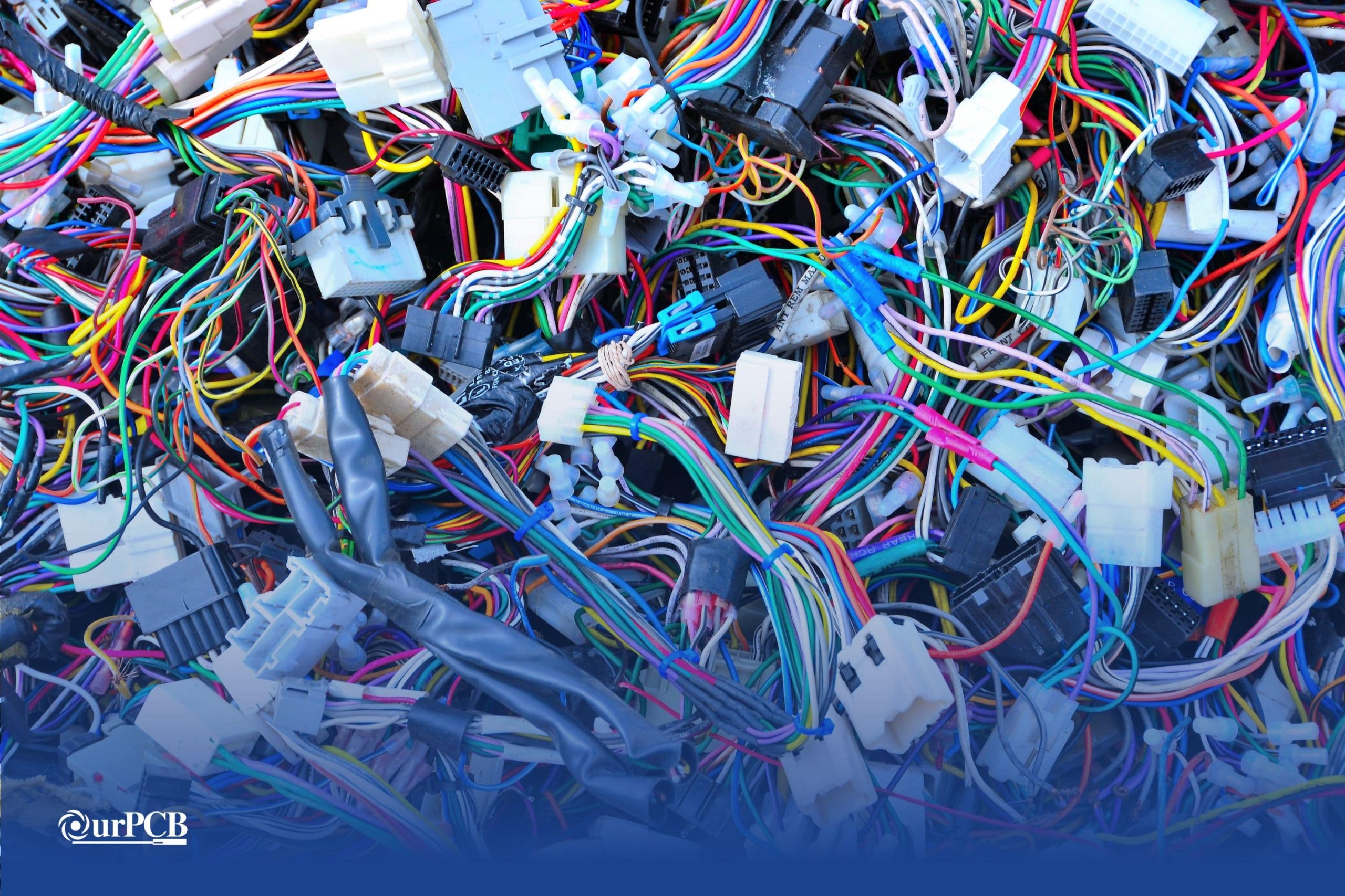
These connectors come in various series, each designed for specific applications and requirements. Here’s a detailed look at some of the most popular JST connector types.
JST-ZH Series
JST-ZH connectors are known for their high-density design and small size. They have a pitch of 1.5mm and are commonly used in compact applications like RC models and small consumer electronics.
JST-PH Series
A popular choice for applications needing a small but reliable connection. A 2.0mm pitch connector, JST-PH series connectors are often used in battery connections, portable devices, and numerous consumer electronics. This series is known for its durability and ability to handle moderate currents.
JST-XH Series
JST-XH connectors are widely used in devices that rely on a robust and secure connection. With a pitch of 2.5mm, they are ideal for connecting multiple components in consumer electronics, LED lighting, and automotive systems.
JST-PA/XA Series
These feature a pitch of 2.0mm and are available in different configurations to meet diverse requirements, including wire-to-wire connections. JST-PA/XA connectors are typically found in household appliances, industrial equipment, and automotive systems.
JST-EH Series
The JST-EH connectors offer a compact and reliable connection. This 2.5mm pitch connector is commonly used in power supplies, industrial control systems, and several consumer electronics. They provide a secure fit and are easy to assemble.
JST-SM Series
Renowned for their hardiness and ability to handle high currents. With a pitch of 2.5mm, you’ll find JST-SM series connectors in LED lighting, automotive applications, and power connections. They provide a strong, secure connection even in demanding environments.
JST-RCY Series
Also known as JST-BEC, these are specifically designed for battery connections in RC models and drones. With a 2.5mm pitch, they give you a reliable and stable connection for power transmission, which makes JST-RCY connectors a preferred choice in the RC markets.
JST-SH/SR Series
These connectors are ultra-compact with a 1.0mm pitch, so they are great for high-density applications. JST-SH/SR connectors are commonly found in compact electronic devices, wearable technology, and medical equipment. Moreover, they offer a reliable connection in a very small form factor.
JST-SHD Series
A step-up in robustness compared to the SH series, also with a pitch of 1.0mm. JST-SHD connectors are designed for more demanding applications that need a secure and durable connection. They are especially effective in high-vibration environments like automotive and industrial machinery.
JST-GH Series
JST-GH connectors are small, but known for being exceptionally reliable. Featuring a 1.25mm pitch, they are designed to handle moderate currents. These connectors are often used in compact electronic devices, drones, and robotics.
JST-VH Series
Designed for high-power applications and featuring a 3.96mm pitch. They are popular in power supplies, industrial equipment, and automotive applications. JST-VH connectors can handle high currents with ease, so these connectors are a good choice for demanding environments.
Special Offer: Get $100 off your order!
Email [email protected] to get started!
Technical Specifications of JST Connectors
Pin-to-Pin Pitch
Pin-to-pin pitch is the distance between the centers of adjacent pins in a connector. JST connectors offer a range of pitches to accommodate different circuit board designs. Common pitches include:
- 1.0 mm
- 1.25 mm
- 2.0 mm
Current and Voltage Ratings
The current and voltage ratings of JST connectors vary based on the connector series and pin size. Here are some examples:
- ZH series: 1.0 A, 50 V
- PH series: 2.0 A, 100 V
- XH series: 3.0 A, 250 V
- EH series: 3.0 A, 250 V
Wire Sizes
JST connectors are compatible with a range of wire sizes (from 28 AWG to 16 AWG), allowing for diverse applications. The wire gauge compatibility typically depends on the connector series. For instance:
- ZH series: 28 to 32 AWG
- PH series: 24 to 30 AWG
- XH series: 22 to 28 AWG
- EH series: 22 to 28 AWG
Shrouds and Locks
Shrouds protect against dust and accidental disconnections, while locks give you a secure connection that resists vibration and mechanical stress. Examples include:
- PH series: Friction locks to prevent accidental disconnection
- XH series: Fully shrouded headers for added protection
Benefits of JST Connectors Applied in PCB Manufacturing
JST connectors are a popular choice in printed circuit board (PCB) manufacturing due to their reliable performance and versatility. Here are some specific benefits:
Improved Connection Reliability
JST connectors’ precise engineering means you have tight connections that resist vibration and environmental factors. They also have a low contact resistance, which minimizes the risk of signal loss and improves overall device performance.
Enhanced Design Flexibility
One of the biggest advantages of using JST connectors in PCB manufacturing is that they come in various sizes, shapes, and pin configurations. This broad selection provides engineers with multiple options to choose the best connector for their specific design requirements. They are also very easy to install and remove, which simplifies the assembly and maintenance processes.
Cost-Effectiveness
JST connectors are cost-effective solutions for PCB manufacturing. Their high reliability reduces the need for frequent replacements and repairs, saving costs in the long run. They’re also widely available and competitively priced.
How to Choose the Right JST Connector for Your PCB
When choosing a JST connector for your PCB, you’ll need to have a good understanding of your project’s needs. They come in various series, each with different specifications, so you’ll need to find the one that’s most suitable for your needs.
At OurPCB, we only use the best JST connectors in our designs. We’ve summarized our recommendations for what to consider when choosing a JST connector for your project below.
| Specification | Overview | Notes and Examples |
|---|---|---|
| Current Rating | Maximum current the connector can handle | To avoid overheating and damage, choose a connector that can accommodate the expected current |
| Voltage Rating |
|
|
| Pin Count |
|
|
| Temperature | Ensure the connector can withstand environmental conditions | Most JST connectors operate within -13°F to 185°F |
| Humidity | Use connectors with protective features for humid environments | Consider sealed versions or connectors made from corrosion-resistant materials |
| Signal Connections |
|
|
| Power Connections |
|
|
How to Integrate JST Connectors into PCB Design
Integrating these connectors into your PCB design involves several key steps to ensure a secure and efficient connection. Here’s what you need to look at.
Footprint Design
Creating a proper footprint for your JST connector is crucial for a reliable connection. Here are the steps to design an effective footprint:
- Obtain Manufacturer’s Datasheet: Start by downloading the JST connector’s datasheet. It contains detailed dimensions and specifications needed for footprint creation.
- Define Pad Dimensions: Using the datasheet, define the pad dimensions on your PCB layout software. Make sure the pads are not too large nor too small to avoid soldering issues.
- Pad Spacing: Ensure the pads are spaced according to the connector’s pin pitch. This keeps each pin aligned correctly with the PCB pads.
- Add Solder Mask: Include a solder mask layer around the pads to prevent solder bridges during assembly.
- Drill Holes for Through-Hole Connectors: If you’re using a through-hole JST connector, include the appropriate drill holes for pin insertion.
Placement and Orientation
Proper placement and orientation of JST connectors on the PCB help make assembly easier and keep the circuit board functioning correctly.
- Accessibility: Place connectors near the edge of the PCB for easy access. Ensure there’s enough clearance around the connector for the mating connector to be inserted and removed without obstruction.
- Orientation: Orient the connectors in a way that matches the design of your device. This can help in preventing misalignment and incorrect connections.
- Mechanical Stability: Position connectors where they can be mechanically supported, reducing stress on solder joints. Avoid placing them on the edge where they might get damaged.
Routing and Clearance
Routing the traces and ensuring proper clearance is necessary for signal integrity and avoiding shorts.
- Trace Width and Spacing: Use the recommended trace width and spacing as per the current rating of the JST connector. This ensures safe and reliable operation without overheating.
- Clearance: Maintain enough clearance between the traces connected to the JST connector and other components. This helps avoid shorts and electromagnetic interference.
- Ground Plane: If possible, place a ground plane under the JST connector to improve signal integrity and provide a return path for signals.
- Via Placement: For multi-layer boards, place vias carefully to ensure they don’t interfere with the connector’s footprint and pads.
Soldering Techniques
Using proper soldering techniques ensures you create a durable and reliable connection. This is crucial for making sure your PCB is effective.
- Solder Paste Application: For surface-mount JST connectors, apply solder paste accurately using a stencil. Distribute it evenly to avoid too much or too little solder.
- Reflow Soldering: Use a reflow oven for surface-mount connectors. Follow the temperature profile recommended by the connector’s datasheet.
- Hand Soldering: For through-hole connectors, hand soldering can be used. Heat the pad and pin evenly and apply solder to ensure it flows around the pin.
- Inspection: After soldering, inspect the joints for cold solder joints or bridges. Use a microscope if necessary to ensure all connections are solid.
JST Connectors: Common Issues and Troubleshooting
Loose Connections
Loose connections in JST connectors can lead to intermittent or complete loss of electrical contact. This can cause devices to malfunction or stop working altogether.
Troubleshooting Steps
- Check the Fit: Make sure the connectors are fully seated by pressing them firmly together. Listen for a clicking sound, indicating a secure connection.
- Inspect for Wear: Look for signs of wear or damage on the connector housing and pins. Replace if necessary.
- Secure the Connection: Use cable ties or adhesive mounts to secure the connectors in place, reducing the risk of vibrations causing disconnections.
Damaged Pins
Damaged pins can disrupt the electrical connection, leading to poor performance or failure of the connected device.
Troubleshooting Steps
- Visual Inspection: Examine the pins for bending, breakage, or corrosion. Straighten bent pins carefully with a small tool, or replace them if they’re severely damaged.
- Cleaning: Clean the pins with a soft brush or compressed air to remove any debris or corrosion. For persistent corrosion, use a contact cleaner specifically designed for electronic components.
- Replacement: If the pins are too damaged to repair, consider replacing the entire connector to restore proper functionality.
Incorrect Wiring
Incorrect wiring can lead to short circuits, incorrect operation of the device, or complete failure of the electrical system.
Troubleshooting Steps
- Verify Wiring Diagrams: Cross-check the wiring against the provided diagrams or schematics. Make sure each wire is connected to the correct pin.
- Use Labels: Label wires clearly during assembly to avoid confusion and make sure they’re connecting properly.
- Check Crimps: Inspect the crimped connections to make sure they are secure and have good electrical contact. Re-crimp or replace any loose or improperly crimped connections.
JST Connector FAQs
How do JST Connectors Compare to Other Connector Types?
JST vs. Molex
JST connectors are typically more compact than Molex connectors, ideal for applications where space is limited. Being larger, Molex connectors usually offer higher current and voltage ratings compared to JST connectors.
Molex connectors generally feature a more user-friendly design. JST connectors can sometimes be more challenging to disconnect due to their smaller size and tighter fit. JST connectors also tend to be less expensive due to their simpler design and smaller size.
JST vs. Dupont
JST connectors are designed with a specific housing and pin configuration and have a more secure connection. Dupont connectors have a simpler design and are often used in breadboarding and prototyping.
While JST connectors have specific current and voltage ratings based on their series, Dupont connectors don’t have standardized ratings. However, Dupont connectors are easier to assemble and customize because they often use crimp pins that can be inserted into various housings.
Where Else Are JST Connectors Used?
- Consumer Electronics: Smartphones, cameras, LED strips, battery packs
- Automotive Applications: Lighting systems, infotainment
- Industrial Equipment: Robotics, control systems
- DIY Projects: Popular among electronics hobbyists for DIY projects
Back to Top: JST Connector | Connectors JST, JST Plug, JST Terminals
Special Offer: Get $100 off your order!
Email [email protected] to get started!


