Electrical noise is common in direct current digital circuits. The noise is primarily an AC signal that, if uncontrolled, will affect the flow of current. Hence, it is essential to eliminate it via the use of a ceramic capacitor. But not all types of capacitors can perform this duty. Real capacitors are primarily for storing electric charges. Therefore, a special kind is necessary for this critical process. A bypass capacitor is a significant component that ably controls the current filtering process.
Let's delve into the basics of this capacitor and its critical applications.
Contents
What is a Bypass Capacitor?
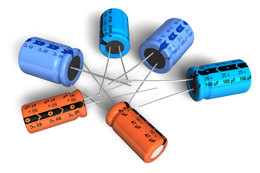
Electrolytic Capacitors
A bypass capacitor removes AC noise on the power supply from a DC signal by shorting it. Thus, it enables the realization of a clean DC signal.
Power supply noise is commonplace with DC signals. However, the noise is problematic and distorts the transient current flow. Thus, connecting a bypass capacitor to the power source eliminates the noise significantly.
Emitter Bypass Capacitor
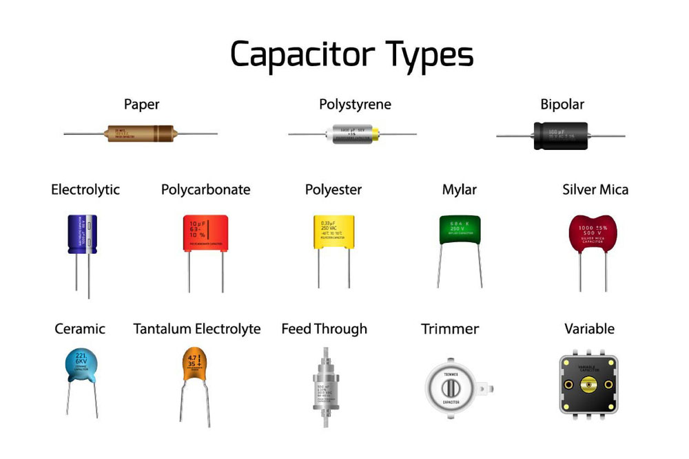
Types of Capacitors
The addition of an emitter resistance to a common emitter amplifier causes a reduction of the device's voltage gain. However, there is also an increase in the circuit's input impedance.
But, when you connect a bypass capacitor parallel to the emitter resistance, the amplifier's voltage gain increases.
On the other hand, the removal of the capacitor results in a reduction in the voltage gain.
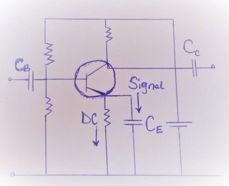
Emitter Bypass Capacitor
Cathode Bypass Capacitor
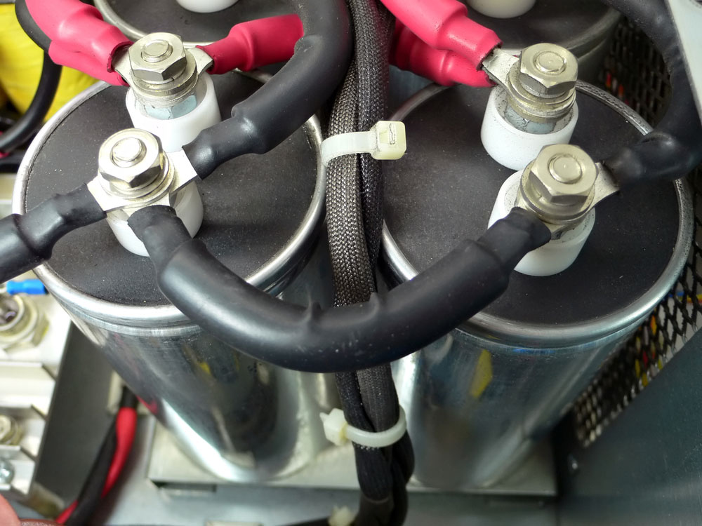
High Voltage Electrical Capacitors
The use of a large capacitor in a conventional triode preamp is essential in eliminating negative feedback. The feedback is primarily due to a cathode resistor in the circuit, and its disadvantage is that it increases gain.
A larger capacitor is highly effective in eliminating the feedback than a small type. Also, it short circuits the audio frequencies in the circuit. Nonetheless, the capacitor will at the same time allow passage of DC.
Therefore, there is a DC bias in the circuit. It is through this process that the bypass capacitor eliminates the noise signal.
Also, note that it is possible to introduce a treble boost via using a smaller capacitor. Thus, it's possible to control the degree of negative feedback based on current demands.
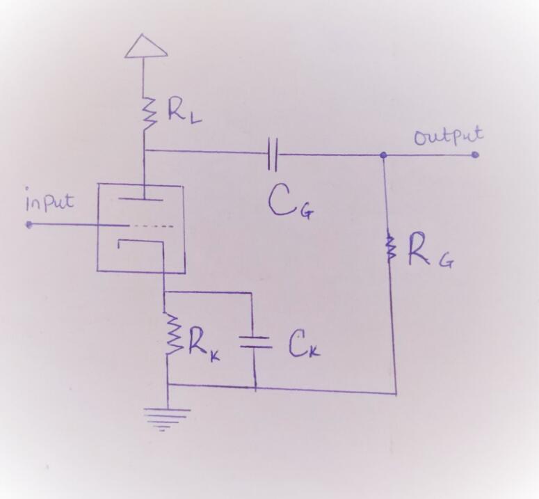
Cathode Bypass Capacitor
Special Offer: Get $100 off your order!
Email [email protected] to get started!
Applications of Bypass Capacitors
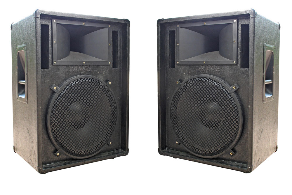
A Bypass Capacitor between an Amplifier and Loudspeaker improves Sound Quality.
- In DC/DC converters
- In audio correction
- Signal coupling and decoupling
- In pass filters (both high and low)
- The DSL amplifiers
- In power factor correction
- The voltage reference
- In clock calendars featuring EEPROM
Difference Between Bypass and Decoupling Capacitor
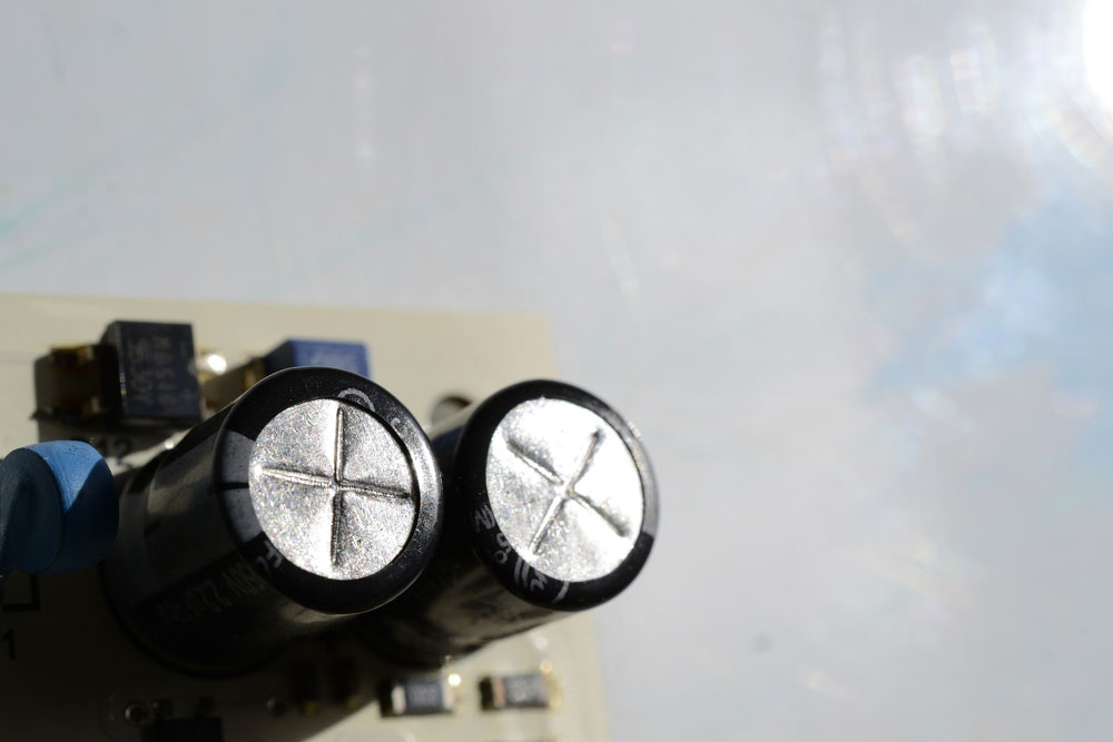
Two Capacitors on a Circuit Board
There are no distinct, noticeable differences between the two capacitors, and they perform similar functions, albeit in different fashions.
| Bypass Capacitor | Decoupling Capacitor |
| Inhibits entry of unwanted noise into the circuit | Separates AC from DC signal thus facilitates improving signal integrity |
| Requires a single electrolytic capacitor to function | The decoupling process requires two different kinds of capacitors. |
How to choose the value of the bypass capacitor
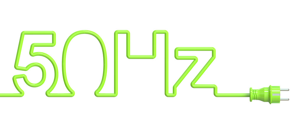
The Standard AC Frequency in most Countries is 50 HZ
Selecting the value of a capacitor is a straightforward process. The ideal reactance value is 1/10th the emitter resistance (RE). Also, the value is dependent on the frequency signals of the AC.
For low-frequency noise, a capacitor of between 1 µF and 100 µF will work effectively. On the other hand, a high-frequency noise requires typical values of between 0.01 µF and 0.1 µF.
The rationale behind these values is that electric current takes the shortest resistance path. Thus, the capacitor will manipulate the resistance of the load current values.
If you want to calculate the actual value of the bypass capacitor, use the formula:
C = 1/2πf.C
Example:
Find the capacitance across a signal path of 440 ohms resistance and a standard frequency of 50Hz.
Solution:
Earlier, we said that the reactance is 1/10th of the resistance. Hence in this case, reactance is 440 ohms/ 10 = 44 ohms.
Hence, the ideal bypass capacitance= 1/2(π) x 50 x44 = 73µF.
Apply the formula to calculate the bypass capacitance of any circuit.
How to place a PCB bypass capacitor
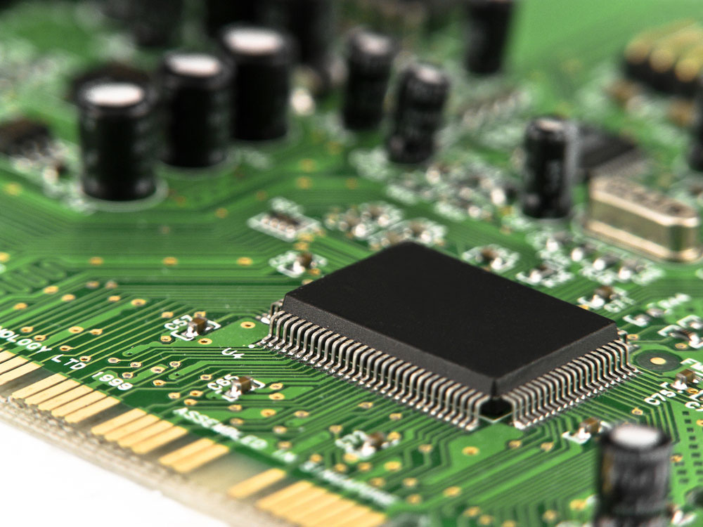
Several Capacitors and Microchips on a PCB
There is a wide range of considerations when placing a bypass capacitor. Note that poor placement will hamper their functionality. Hence, the proper order is as significant as using the accurate capacitor size.
Consider the following tips during placement of a primary bypass capacitor in integrated circuits:
- Place the bypass components at the bottom of the board. While at the bottom, they free up space for placement of vias and other features.
- If you have multiple bypass capacitors on the same IC, locate the lowest value capacitor near the IC's pin.
- If you have a large assortment of non-polarized and tantalum capacitors, locate them near the IC's pin. Ensure that you place them in ascending order of their capacitances.
- When dealing with devices with multiple power pins, use a bypass capacitor for every nail. And it will help solve ground bounce problems.
- Lastly, ensure you keep referring to the schematic when placing bypass resistors. And it will help prevent placing them at tied, high logic pins.
Conclusion
So now you have all the insights about bypass resistors. And we have also equipped you with the necessary details of how to use it in a PCB. If you are a DIY enthusiast, you can use the above information to control parasitic resistance in your projects.
Also, if there is anything that is still unclear about bypass capacitors, feel free to reach us. We are always ready to respond to your queries in the shortest possible time.
Special Offer: Get $100 off your order!
Email [email protected] to get started!


