Strain Gauge Load cells are force transducers that transform kinetic energy into an electrical output. Often, the signal strength varies with force. A strain gauge, pneumatic, and hydraulic load cells are the three simple load-type cells.
Today's article will focus on strain gauge load cells and their wide range and distinct applications. Furthermore, we'll introduce its types, working principles, and construction.
Contents
- What is a strain gauge load cell?
- Construction of strain gauge load cell
- How Does a Load Cell Work?
- Wheatstone bridge of a load cell
- Operation of strain gauge Load cell
- Case One
- Case Two
- Uses of Strain Gauge Load Cell
- Advantages and Disadvantages
- Strain Gauge Load Cell: Advantages
- Strain Gauge Load Cell: Disadvantages
- What are the types of Load Cells?
- How to choose a load cell for your application?
- Conclusion
What is a strain gauge load cell?
A strain gauge load cell is a gadget that measures electrical resistance changes after applying a force/load to it. Structurally, it has fine foil/wire arranged in a grid pattern to generate linear resistance change when vertically straining a single axis.

(Ultrasonic sensor module)
For more accurate readings, the load cell uses several strain gauges. Therefore, a full bridge has four active strain gauges, a half-bridge has two, and a quarter bridge has only one active strain gauge.
Construction of strain gauge load cell
There is a steel cylinder composed of four mounted strain gauges. Then, mounting two strain gauges (R4 and R1 vertical) often occurs along the applied load's direction, as displayed in the diagram below.
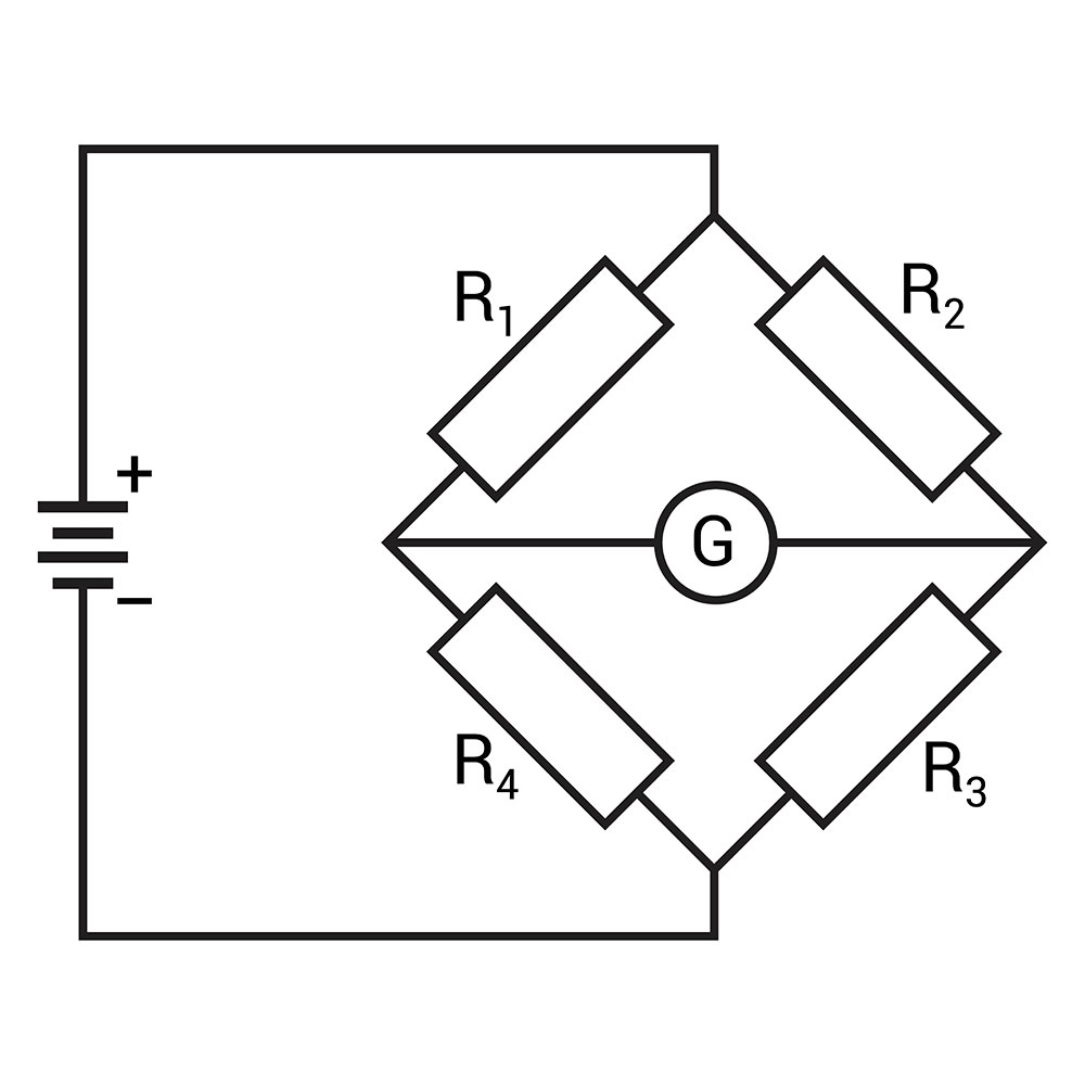
(Wheatstone bridge in a load cell with four strain gauges, R1, R2, R3, and R4)
Contrarily, the remaining two (R3 and R2 horizontal gauges) have a circumferential mounting of 90° to the vertical gauges.
How Does a Load Cell Work?
The output resistance changes in strain gauges usually differ in compression vs. tension load cells. For instance, a compression load/force decreases the resistance by keeping the strain gauge shorter and thicker. On the other hand, tension force increases the strain gauge resistance because it gets longer and thinner.
The gauge has an attachment to a carrier, which attaches to a load cell and ensures the strain gauge experiences the load cell’s strain.
A single strain gauge measures a minute resistance change (approximately 0.12Ω). For that reason, you can employ several strain gauges to increase the sensitivity of the load cell. The most effective way is through a Wheatstone bridge.
Wheatstone bridge of a load cell
Here, strain gauges replace the balanced resistors in the Wheatstone bridge configuration by alternating between measuring compression and tension. If you apply a force to the load cell, there's a resistance change in the strain gauges, and you can measure the output (VO)/G.
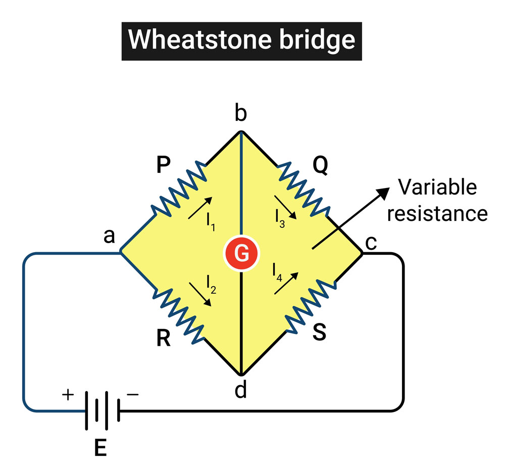
(Wheatstone bridge circuit)
Next, use the equation below to determine the value of VO/Voltage output.
| VO = | R3 | – | R2 | × VEX | ||
| R3 + R4 | R1 + R2 |
Special Offer: Get $100 off your order!
Email [email protected] to get started!
Operation of strain gauge Load cell
We will use two cases to explain how a strain gauge load cell operates.
Case One
Here, the four gauges have a similar resistance if you haven’t applied any force or mechanical load on the cylinder. And since the P and N terminals possess the same potential, your output voltage becomes zero because there’s a wheat stone bridge balance.
Case Two
Secondly, let’s say you introduce a force on the cylinder for load measurement. As a result, you’ll compress R4 and R1 and reduce their resistance.
However, R3 and R2 horizontal gauges will experience tension and increase their resistance. Straining the changes varies their resistance.
Our P and N terminals have discrete potentials with variations in the electrical output voltage. The change in voltage is due to the applied force/load, and you can measure it after calibration.
Uses of Strain Gauge Load Cell
Often, technologists use a strain gauge load cell in the following scenario and application.
- First, when the load is unsteady.
- Then, industrial applications like crane load monitoring, tool force dynamometers, and vehicle weighbridges.
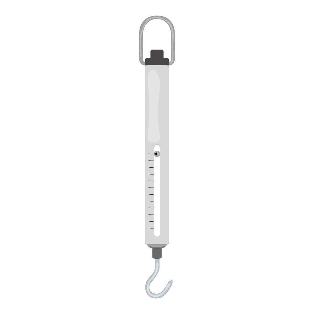
(dynamometer)
Advantages and Disadvantages
Some of the most common benefits of a strain gauge load cell include the following;
Strain Gauge Load Cell: Advantages
- Besides compact size, it is also cost-effective.
- In addition, it has low hysteresis and good sensitivity.
- It has several mounting options, customized shapes, and geometries per your requirement.
- Its construction material (high-strength aluminum or stainless steel) makes it durable and robust. It enables minimal deformity and ensures the gauge resumes its original shape after removing the load.
- Furthermore, you are at liberty to choose from the various capacities with ranges between 10 grams and 100K pounds.
- It also has a good accuracy level that favors machinery in aerospace, surgical robotics, etc.
- Finally, you can achieve the highest performance rate with the load cell despite having rigorous conditions. It's no surprise that some designs are capable of billions of lifespans (fully reversed cycles).
Strain Gauge Load Cell: Disadvantages
However, there are a few limitations.
- Usually, a non-axial force affects its performance.
- Also, if you apply excessive force or stress to the cell, you may permanently damage it.
- Lastly, it needs a network that compensates for its temperature variations.
What are the types of Load Cells?
Different strain gauge load cells depend on distinct geometries and body shapes.
- In-Line Load Cell/ Column or canister-style force sensor/ In-line force transducer; The load cell has male threads and works best in compression and tension loading applications due to its high stiffness and high accuracy. Moreover, it requires less mounting clearance.
- Load Button; They possess a flat raised surface where you apply a compressive force. Then, their robustness, compactness, and low-profile designs make them ideal for fatigue applications.
- S-Type/ Z-Beam/ S-Beam Load Cell; It is also a compression and tension force transducer but has female threads. Apart from its compact profile and thin beam, it also has highly accurate measurements. Thus, it favors applications like automated control feedback and in-line processing.
Strain Gauge Load Cell: Washer/ Donut/ Thru-Hole Load Cell;
- It’s different from the rest because of its smooth non-threaded inner diameter. Generally, it quantifies compressive loads that need rods passing through their centers. It is often recommendable in measuring bolt loading.
- Universal/ Canister-style/ Pancake Load Cells; The type of load cell centrally-threaded holes measure compression or tension loads. You’ll mostly find them in applications of high capacity, high fatigue life, and high endurance in-line measurements. Additionally, they've got high resistance toward off-axis loading.
- Rod-End Load Cell; The gauge force sensor type has a female and male thread for your mounting purposes. As such, it often suits applications requiring force sensors to adapt to an already existing fixture.

( measures compression and tension)
How to choose a load cell for your application?
Here’s an easy guide that’ll help you tone down the numerous options when choosing a load cell.
- First and foremost, know your application plus what you’ll measure. Often, load sensors measure compression or tension loads.
- Secondly, describe the features of your load sensor mounting and how you’ll assemble it. Here, you’ll choose between a dynamic load or a static one alongside their respective mounting type.
- Next, describe the maximum and minimum capacity specifications. It involves extraneous loads like off-center and side loads and the maximum operating load.
- Then, acknowledge the mechanical performance requirements like frequency bridges, resolution, bridge resistance, etc. Additionally, have geometry and size requirements such as length and height. Other features include redundant or multiple bridges, high temperature, and cryogenic.
- Lastly, know the electrical output signal type an application needs. Notably, the output voltage in a force transducer circuit is mV/V. Thus, if a DAQ or PLC application needs serial communication, digital output, or analog output, you’ll settle for an electrical signal conditioner or load cell amplifier. The right amplifier and system calibration will ensure high accuracy and system compatibility.
(lambda Sensor Close-up)
Conclusion
Briefly, a strain gauge load cell is a load cell type with a strain gauge assembly. The gauges placement is within the load cell housing and they transform a force/load into an electrical signal.
Today we’ve outlined important factors you should know about the load cell, i.e., its working principle, usage, types, merits and demerits.
That’s all for this article. We hope it is useful for you. Thanks for your time.
Special Offer: Get $100 off your order!
Email [email protected] to get started!


