An RFID is a piece of standard tracking equipment that we can use in our day-to-day life. RFID tags revolutionized the world of business where it made it simple to keep track of goods and manage data. The usage of RFID is not only limited to companies that have inventory but can also be usable in casino chips and other tracking tasks like pet tracking. So, this article will highlight more about the EM18 RFID reader. For everyone in the tracking world and electronics enthusiasts, this will be a complete guide to the EM18.
Contents
What is em 18?
To begin with, RFID (Radio-Frequency Identification) is a wireless technology that employs the use of radio waves to identify whether an RFID tag is present.
To better understand, let’s take a bar code reader instance. For it to work, you need to optically scan the bar in front of a reader to take stock like they do in supermarkets. But with RFID, you do not need to watch whatever you want, as long as it is within the radio wavelength that the RFID is transmitting.
The RFID comes with a tag and a reader, where the EM18 falls in. It quickly scans and reads ID tags within a specific radiofrequency. The RFID reader has a fixed transceiver and antennae to receive the signals. So, if an ID is within a particular range, the reader will sense it and transmit this information to the microcontroller or PC.

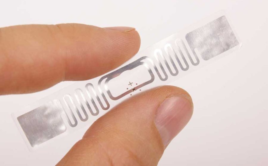
(RFID tags)
Em-18 Pin Configuration
The EM-18 bears a nine-pin configuration whereby seven of the pins are connected, and two aren’t. Below is a table of the em-18 design.
| Pin No. | Pin Name | Purpose |
| 1 | VCC | Connects the positive side of the power source to the device |
| 2 | GND | the ground |
| 3 | BUZZ | Connected to the buzzer |
| 4 | NC | No use |
| 5 | NC | No use |
| 6 | SEL | If HIGH, it uses RS232. If Low, it uses WEIGAND |
| 7 | TX | Data is communicated through TX via RS232 communication |
| 8 | DATA1 | WEIGAND DATA 1 HIGH pin |
| 9 | DATA0 | WEIGAND DATA LOW pin |
Special Offer: Get $100 off your order!
Email [email protected] to get started!
Features and Specifications
The EM18 comes with a set of very unique and specific features and specifications.
- +4.5 V to +5.5 V Operating voltage
- A 50mA current consumption power
- Wide range of operating temperature of between 0ºC to +80ºC
- Functions with low power supply
- 125KHz operating frequency
- Integrated antennae
- Reading circumference of 10 centimeters depending on tag location
- 9600bps communication parameter
Working Principle of EM-18 RFID Module
The working principle of EM18 is about using radio waves to identify a specific RFID tag. So generally, the reader gives out a 125KHz frequency through its coils, and if a similar 125KHz passive RFID tag is within the frequency field, it gets energized. On the other hand, the tag will consist of a CMOS IC, ensuring that the tags are always powered.
So once the tags receive the information of being in the same frequency as the reader, it will use this information and send it as storable data in a programmed memory. This way, it will be easily identified by the reader.
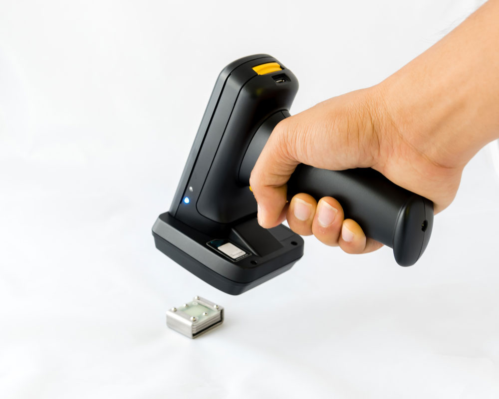
(a bar code scanner in use)
How to use the EM-18 RFID module?
As stated above, the EM18 is a sensor module, so we need to identify a mode of communication between the controller and module. Then, we need to ensure that we program the controller to accept the data that the module emits. When you power up the system and the tag is close to the module, it will receive the information and transmit it to the controller. Then, the controller will receive a piece of actionable information that is programmable according to the different purpose functions of the system.
Step 1
Determining the communication mode is the first step. Usually, the EM18 has two methods of output communication, RS2,32, and WEIGAND. The SEL Pin is what determines what way of communication to be used. The RS232, which is the most popular model, is applicable when the SEL pin is selected high, and for the instance when the SEL is set low, the WEIGAND communication comes to action.
Step 2
The controller must be capable of receiving information at a bit rate of 9600bps. The module emits at the same rate, and if there is a mismatch, it will not function properly.
Application
The EM18 finds a lot of use in our day-to-day life. Below is a list of areas of application.
- Theft protection
- Body implants
- Medical tags
- Robotics
- Package Identification
- Data Authorization
- e-Payments
- e-Ticketing for events and trains
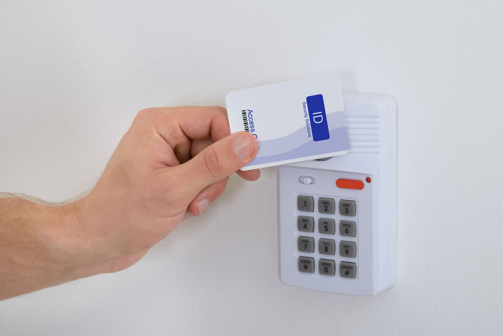
(RFID in use as a card reader)
Conclusion
It is clear how important how the use of RFID was revolutionary to most businesses and our day-to-day lives. However, finding a reliable source of your EM18 modules and controller is critical.
Here at OurPCB, we have experience helping you source high-quality EM18 that you would easily incorporate into your next project. Feel free to contact us today for your next order.
Special Offer: Get $100 off your order!
Email [email protected] to get started!


